
Technical data

104 U1401A User’s and Service Guide
5 Application Examples
Junction Field-Effect Transistor (JFET) Switch Test
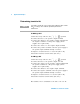
A JFET typically has three terminals, namely drain (D), gate
(G), and source (S). There are two types of JFET depending
on the channel type: p- channel and n- channel. It is
recommended that you obtain the specific data sheet from
the manufacturers. You can also use the U1401A to identify
a JFET by following the procedure below:
1 Turn the rotary switch to the Ω position.
2 Connect the red and black test leads to the positive and
negative input terminals respectively. The positive
terminal will provide a positive test voltage.
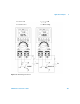
3 In this example, we will use a JFET with TO- 92 package
as shown in Figure 5- 10.
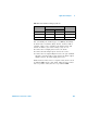
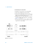
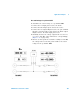
4 Probe pin 1 with the red test lead, and pin 2 with the
black test lead. Then reverse the test leads and obtain the
reading. If both readings are <1 kΩ, you can assume that
these pins are the drain and source terminals. The
remaining pin 3 is the gate terminal. Always find out first
which pin is the gate terminal. Refer to Table 5- 7 on
page 105.
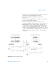
Figure 5-10 TO-92 JFET
Most TO-92 JFET
will have pin 1 as
the drain.