
Technical data
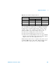

102 U1401A User’s and Service Guide
5 Application Examples
Determining transistor h
fe
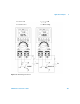
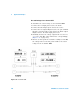
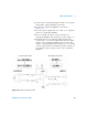
For NPN-type BJT
1 Turn the rotary switch to the / position.
2 Connect the base to the positive output terminal.
3 Connect the emitter to the negative output terminal and
the negative terminal of a DC power supply (which
supplies the required V
DD
).
4 Connect the collector to the negative input terminal.
5 Connect the positive terminal of the DC power supply to
the positive input terminal through a resistor.
6 Output a constant current of +1.000 mA (this is I
B
).
7 Read the measured current value (this is I
C
).
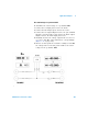
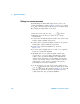
For PNP-type BJT
1 Turn the rotary switch to the / position.
2 Connect the base to the positive output terminal.
3 Connect the collector to the negative output terminal and
the positive terminal of a DC power supply (which
supplies the required V
DD
).
4 Connect the emitter to the negative input terminal.
5 Connect the negative terminal of the DC power supply to
the positive input terminal through a resistor.
6 Output a constant current of - 0.500 mA (this is I
B
).
7 Read the measured current value (this is I
C
).
The transistor h
fe
is calculated as the ratio of I
C
over I
B
.
NOTE
If you wish to obtain the correct results, please adjust the values of V
DD
and I
B
according to the conditions specified by the transistor
manufacturer.