
Technical data

Application Examples 5
U1401A User’s and Service Guide 99
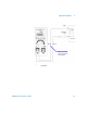
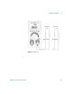
5 Probe the base terminal with the red test lead, and the
other two pins (in turn) with the black test lead. Record
the readings.
6 Repeat step 5, but reverse the red and black test leads.
Record the readings.
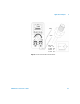
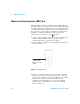
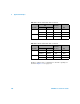
7 The polarities (NPN or PNP) and terminals can be
identified by referring to Table 5- 3, Table 5- 4 and
Table 5- 5. V
be
is always greater than V
bc
. Most TO- 92
transistors will have pin 1 as the emitter. It is
recommended that you check and verify with the specific
data sheet from the manufacturer.
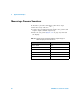
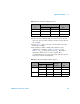
Table 5 - 2 Base terminal according to probe test
Pin
Probe
BaseRed/Black Black/Red
1-2 OL OL 3
1-3 OL OL 2
2-3 OL OL 1
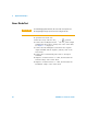
Table 5 - 3 Polarity and terminals if Pin 3 is the base
Test l ead s
Pins
Te rm i na ls
(V
be
>V
bc
) Ty p e3-1 3-2
Red/Black 0.6749 V 0.6723 V ECB NPN
0.6723 V 0.6749 V CEB NPN
Black/Red 0.6749 V 0.6723 V ECB PNP
0.6723 V 0.6749 V CEB PNP