
Technical data

98 U1401A User’s and Service Guide
5 Application Examples
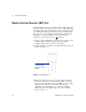
Bipolar Junction Transistor (BJT) Test
A BJT typically has three terminals, namely emitter (E), base
(B), and collector (C). There are two types of BJT depending
on polarity: PNP type and NPN type. It is recommended that
you obtain the specific data sheet from the manufacturers.
You can also use the U1401A to identify the polarity and
terminals of a BJT by following the procedure below:
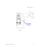
1 Turn the rotary switch to the position.
2 Connect the red and black test leads to the positive and
negative input terminals respectively. The positive
terminal will provide a positive test voltage.
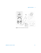
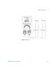
3 In this example, we will use a BJT with TO- 92 package as
shown in Figure 5- 7.
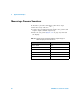
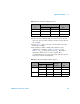
4 Probe pin 1 with the red test lead, and pin 2 with the
black test lead. If the measured value is OL, reverse the
probes. If the measured value is still OL, you can assume
that these two pins are the emitter and collector
terminals. The remaining pin 3 is the base terminal.
Always find out first which pin is the Base terminal.
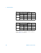
Refer to Table 5- 2.
Figure 5-7 TO-92 Transistor
Most TO-92
transistors will
have pin 1 as the
emitter.