
Technical data


90 U1401A User’s and Service Guide
5 Application Examples
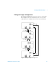
Simulating a 2-wire transmitter on a current loop
The special yellow test lead supplied with the U1401A can
also be used for simulating a 2- wire transmitter. This lead is
used in place of the red lead (which is used in most other
applications). It protects the instrument from high loop
voltages, and it also has the advantage of using the same
two output terminals for all applications.
1 Turn the rotary switch to any one of the /
or / positions.
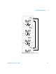
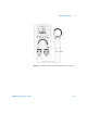
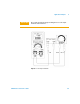
2 Connect the special yellow test lead between the positive
output terminal of the instrument and the input terminal
of the measurement device on the current loop. Refer to
Figure 5- 3 on page 91.
3 Connect the black alligator lead between the negative
output terminal of the instrument and the current loop
excitation source. Make sure the polarity is correct.
4 Set the current level between 0 mA and 20 mA. Do not
set a negative current output value.
5 Press OUTPUT to output the test current.
This connection can be used for any loop voltage from 12 V
to 30 V.
CAUTION
Do not apply an external voltage exceeding 30 V across the output
terminals of the instrument.