U1401A Handheld Multi-Function Calibrator/Meter User’s and Service Guide Agilent Technologies
Notices © Agilent Technologies, Inc. 2009 - 2012 Warranty No part of this manual may be reproduced in any form or by any means (including electronic storage and retrieval or translation into a foreign language) without prior agreement and written consent from Agilent Technologies, Inc. as governed by United States and international copyright laws. The material contained in this document is provided “as is,” and is subject to being changed, without notice, in future editions.
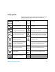
Safety Symbols The following symbols on the instrument and in the documentation indicate precautions which must be taken to maintain safe operation of the instrument.
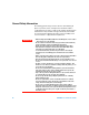
General Safety Information The following general safety precautions must be observed during all phases of operation, service, and repair of this instrument. Failure to comply with these precautions or with specific warnings elsewhere in this manual violates safety standards of design, manufacture, and intended use of the instrument. Agilent Technologies assumes no liability for the customer’s failure to comply with these requirements. WA R N I N G IV • When working above DC 60 V, AC 30 Vrms or AC 42.
WA R N I N G CAUTION U1401A User’s and Service Guide • Do not substitute parts or modify equipment to avoid the danger of introducing additional hazards. Return the product to the nearest Agilent Technologies Sales and Service Office for service and repair to ensure the safety features are maintained • Do not operate damaged equipment as the safety protection features built into this product may have been impaired, either through physical damage, excessive moisture, or any other reason.
Environmental Conditions This instrument is designed for indoor use and in an area with low condensation. The table below shows the general environmental requirements for this instrument. CAUTION Environmental conditions Requirements Operating temperature Full accuracy from 0 °C to 40 °C Operating humidity Full accuracy up to 80% R.H. (relative humidity) for temperature up to 31 °C, decreasing linearly to 50% R.H.
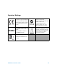
Regulatory Markings mark shows that the product complies The C-tick mark is a registered trademark of the Spectrum Management Agency of Australia. This signifies compliance with with all the relevant European Legal the Australia EMC Framework Directives. regulations under the terms of the Radio Communication Act of 1992. ICES/NMB-001 indicates that this ISM device complies with the Canadian ICES-001. This instrument complies with the WEEE Directive (2002/96/EC) marking requirement.
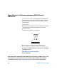
Waste Electrical and Electronic Equipment (WEEE) Directive 2002/96/EC This instrument complies with the WEEE Directive (2002/96/EC) marking requirement. This affixed product label indicates that you must not discard this electrical or electronic product in domestic household waste. Product Category: With reference to the equipment types in the WEEE directive Annex 1, this instrument is classified as a “Monitoring and Control Instrument” product. The affixed product label is as shown below.
In This Guide... 1 Getting Started This chapter contains a brief description of the U1401A Handheld Multi-Function Calibrator/Meter front panel, rotary switch, keypad, display, terminals, and rear panel. 2 Calibrator Output Operations This chapters contains detailed information on how to generate signals using the U1401A. 3 Making Measurements This chapter contains the detailed information on how measurements are taken using the U1401A.
Declaration of Conformity (DoC) The Declaration of Conformity (DoC) for this instrument is available on the Web site. You can search the DoC by its product model or description. http://regulations.corporate.agilent.com/DoC/search.htm NOTE X If you are unable to search for the respective DoC, please contact your local Agilent representative.
Contents Contents 1 Getting Started Introducing the U1401A Handheld Multi-Function Calibrator/Meter 2 Standard Purchase Items List of Accessories Product Overview 3 4 5 Slide switch 5 The front panel at a glance 7 The rotary switch at a glance 8 The keypad at a glance 9 The display at a glance 13 The terminals at a glance 17 The rear panel at a glance 19 Display selection with the Hz key 20 Display selection with the DUAL key 22 Remote Communication 2 23 Calibrator Output Operations Enabling and Disa
Contents Measuring DC voltage Measuring AC voltage Measuring Current 46 48 49 DC mA measurement 49 Percentage scale of DC mA measurement Measuring Temperature 50 51 Measuring Resistance and Testing Continuity Alerts and Warning During Measurement Overload alert for voltage measurement Math Operations 54 56 56 57 Dynamic recording 57 Relative (zero) 60 Triggering Operations 61 Data hold (manual trigger) Refresh hold (auto trigger) 1 ms peak hold 63 4 61 62 Changing the Default Settings Enterin
Contents Setting the display backlight timer 81 Setting the power saving mode 82 5 Application Examples Source Mode for mA Output 86 Simulation Mode for mA Output 88 Simulating a 2-wire transmitter on a current loop Measuring a Pressure Transducer Zener Diode Test Diode Test 90 92 94 96 Bipolar Junction Transistor (BJT) Test Determining transistor hfe 98 102 Junction Field-Effect Transistor (JFET) Switch Test Operational Amplifier Verification 104 108 Current-to-voltage converter 108 Voltag
Contents Closed-case electronic calibration 129 Agilent Technologies’ calibration services 129 Calibration interval 129 Other recommendations for calibration 130 Environmental conditions 130 Warm up 130 Recommended Test Equipment 131 Performance Verification Tests 132 Self-verification 132 Input performance verification 133 Output performance verification 137 Adjustment Considerations Adjustment Procedures 138 139 Input calibration 139 Output calibration 140 8 Specifications General Specifications
Contents Constant voltage and constant current outputs Square wave output 156 U1401A User’s and Service Guide 155 XV
Contents XVI U1401A User’s and Service Guide
Tables Tables Table 1-1. List of accessories 4 Table 1-2. Slide switch functions 5 Table 1-3. Rotary switch positions and their corresponding functions 8 Table 1-4. Keypad functions 10 Table 1-5. Instructions involving shifted functions 12 Table 1-6. Description of display annunciators 14 Table 1-7. Description of terminals 17 Table 1-8. Overload protection for the input terminals 18 Table 1-9. Measurement functions and corresponding display selection with the Hz key 20 Table 1-10.
Tables Table 7-4. Output performance verification tests 137 Table 7-5. Output voltage calibration steps 141 Table 7-6. Output current calibration steps 142 Table 8-1. DC mV/voltage specifications 147 Table 8-2. DC current specifications 148 Table 8-3. AC mV/voltage specifications 148 Table 8-4. AC current specifications 149 Table 8-5. AC+DC mV/voltage specifications 149 Table 8-6. AC+DC current specifications 150 Table 8-7. Temperature specifications 150 Table 8-8. Frequency specifications 151 Table 8-9.
Figures Figures Figure 1-1. The slide switch 5 Figure 1-2. The front panel 7 Figure 1-3. The rotary switch 8 Figure 1-4. Keypad functions 9 Figure 1-5. Keypad shifted functions 10 Figure 1-6. Full display 13 Figure 1-7. Terminals 17 Figure 1-8. The rear panel 19 Figure 1-9. IR-USB cable 24 Figure 1-10. IR-USB cable connection 25 Figure 1-11. IR-USB cable 25 Figure 2-1. Selecting autoscan output mode 34 Figure 2-2. Example of a typical autoscan output 34 Figure 2-3.
Figures Figure 4-4. Setting the beeper frequency 73 Figure 4-5. Setting the minimum frequency 74 Figure 4-6. Setting the percentage scale readout 75 Figure 4-7. Setting the print mode for remote control 76 Figure 4-8. Setting the echo mode for remote control 77 Figure 4-9. Setting the data bit for remote control 78 Figure 4-10. Setting the parity check for remote control 79 Figure 4-11. Setting the baud rate for remote control 80 Figure 4-12. Setting the display backlight timer 81 Figure 4-13.
U1401A Handheld Multi-Function Calibrator/Meter User’s and Service Guide 1 Getting Started Introducing the U1401A Handheld Multi-Function Calibrator/Meter 2 Standard Purchase Items 3 List of Accessories 4 Product Overview 5 Slide switch 5 The front panel at a glance 7 The rotary switch at a glance 8 The keypad at a glance 9 The display at a glance 13 The terminals at a glance 17 The rear panel at a glance 19 Display selection with the Hz key 20 Display selection with the DUAL key 22 Remote Communication 23
1 Getting Started Introducing the U1401A Handheld Multi-Function Calibrator/Meter The key features of the U1401A are: • Simultaneous signal generation and measurement. • DC, AC, and AC+DC voltage and current measurements. • DC voltage, DC current, and square wave outputs. • Intelligent output and standby control. • Rechargeable Ni- MH battery with built- in charging capability. • Smart charger design without battery removal. • Bright Electroluminescence (EL) backlight with 5- digit LCD display.
Getting Started 1 Standard Purchase Items Verify that you have received the following items with your U1401A Handheld Multi- Function Calibrator/Meter: • Carrying case • Protective holster • Rechargeable battery pack (1.
1 Getting Started List of Accessories Table 1-1 List of accessories Type Agilent part number Standard Description Protective holster Rechargeable battery pack (1.
Getting Started 1 Product Overview Slide switch The slide switch has the following positions: • Charge: Select this position to charge the batteries. Use the AC adapter provided to charge this instrument. • M: Select this position to enable only the measurement functions. • M/S: Select this position to enable both the measurement and source functions. 2 3 1 4 5 6 Figure 1-1 The slide switch Table 1-2 Slide switch functions U1401A User’s and Service Guide No.
1 Getting Started Table 1-2 Slide switch functions (continued) No. Description Function 5 Slide Switch — 6 Charging indication Indicates the charging process.
Getting Started 1 The front panel at a glance Display Keypad Rotary switch Terminals Figure 1-2 The front panel U1401A User’s and Service Guide 7
1 Getting Started The rotary switch at a glance Before powering on the U1401A, set the slide switch to M or M/S position. To switch on the U1401A, turn the rotary switch to the desired function. The input and output functions are selected together. The outer circle indicates the output (source) function while the inner circle indicates the input (meter) function. 3 4 5 2 6 1 Figure 1-3 The rotary switch Table 1-3 Rotary switch positions and their corresponding functions Description/Function No.
Getting Started 1 Table 1-3 Rotary switch positions and their corresponding functions Description/Function No. Input (white) Output (yellow) 5 Diode and continuity tests Constant current: ±25 mA 6 DC, AC, or AC+DC mA measurements: 50 mA or 500 mA • Constant voltage: ±1.5 V, ±15 V • Constant current: ±25 mA • Square wave output The keypad at a glance The operation of each key is shown below. A related annunciator appears on the display and the instrument beeps when a key is pressed.
1 Getting Started 9 8 11 7 Figure 1-5 Keypad shifted functions Table 1-4 Keypad functions No. Key Function when pressed for less than one second Function when pressed for more than one second 1 AC/DC Selects DC, AC, or AC+DC Toggles between peak hold ON or OFF for V and mA measurement 2 HOLD If the data hold mode is enabled: Exits data hold mode[1] Freezes the present measured value. Press again to trigger the next measured value.
Getting Started 1 Table 1-4 Keypad functions (continued) No. Key Function when pressed for less than one second Function when pressed for more than one second 7 SHIFT Enables and disables the shifted functions of the other keys Toggles backlight ON/OFF 8 [3] MODE Selects output modes for constant voltage/constant current, autoscan and autoramp. Selects frequency (Hz), duty cycle (%), pulse width (ms), and level adjustments for square wave output.
1 Getting Started Shifted functions Every key (except the SHIFT key itself) has a shifted function. To access these shifted functions, you must first press SHIFT. After pressing SHIFT, the shifted functions will remain enabled (the LCD display will indicate ) until the SHIFT key is pressed again. Throughout this manual, instructions that involve shifted functions will be given without explicit mention of the SHIFT key.
Getting Started 1 The display at a glance To view the full display (with all segments illuminated), press while turning the rotary switch from OFF to any non- OFF position. After you are done viewing the full display, press any key to resume the normal function, depending on the rotary switch position. The instrument will then enter power save mode if the auto power- off ( ) feature is enabled.
1 Getting Started Table 1-6 Description of display annunciators LCD display annunciator Description Remote control Scan output Ramp output Shifted functions enabled AUTO Autorange Relative mode Low battery indication Auto power-off enabled Square wave output Frequency (Hz), duty cycle (%), pulse width (ms), and level for square wave output Constant current output Constant voltage output 14 U1401A User’s and Service Guide
Getting Started 1 Table 1-6 Description of display annunciators (continued) LCD display annunciator Description Thermocouple type for temperature test. The U1401A supports K-type thermocouple only.
1 Getting Started Table 1-6 Description of display annunciators (continued) LCD display annunciator Description Input units for primary display Square wave output.
Getting Started 1 The terminals at a glance WA R N I N G To avoid damaging this instrument, do not exceed the rated input limit. 1 2 Figure 1-7 Terminals Table 1-7 Description of terminals No. Description Function 1 OUTPUT (Yellow) For constant voltage, constant current, and square wave output functions 2 INPUT (Grey-white) For voltage, current, and resistance measurements, and diode and audible continuity tests This instrument has four terminals.
1 Getting Started Table 1-8 Overload protection for the input terminals Rotary switch position Input terminal Overload protection AC/DC voltage range: 5 V to 250 V + and – 250 Vrms AC/DC voltage range: 50 mV to 500 mV Ohm (Ω) Diode ( ) Temperature AC/DC current range: 50 mA to 500 mA 18 250 V/ 630 mA, fast-acting fuse U1401A User’s and Service Guide
Getting Started 1 The rear panel at a glance Figure 1-8 The rear panel U1401A User’s and Service Guide 19
1 Getting Started Display selection with the Hz key The frequency measurement function is able to detect the presence of harmonic currents in neutral conductors and determines, whether these neutral currents are the result of unbalanced phases or non- linear loads. Press to enter the frequency measurement mode for current or voltage measurements. The voltage or current values will be displayed on the secondary display and the frequency values on the primary display.
Getting Started 1 Table 1-9 Measurement functions and corresponding display selection with the Hz key (continued) Measurement function Primary display Secondary display DC current Frequency (Hz) DC current Duty cycle (%) Pulse width (ms) AC+DC current Frequency (Hz) AC+DC current Duty cycle (%) Pulse width (ms) Current in percentage scale (0 mA to 20 mA or 4 mA to 20 mA) Frequency (Hz) Duty cycle (%) Current in percentage scale (0 mA to 20 mA or 4 mA to 20 mA) Pulse width (ms) U1401A User’s a
1 Getting Started Display selection with the DUAL key Press to enable the dual display function, in which two separate parameters of the measured signal is displayed simultaneously on the primary and secondary displays. The dual display function is not available in dynamic recording or trigger mode. Refer to Table 1- 10.
Getting Started 1 Remote Communication The U1401A has a bidirectional (full duplex) communication capability that makes it very easy to transfer data from the instrument to a PC. The required accessory for this feature is an optional IR- USB cable and the application software in the accompanying CD. To communicate with the personal computer through remote communication: 1 Set up the communication parameters of the instrument and the personal computer you are using.
1 Getting Started reattach the cover, simply slip the cover over the connector. Make sure that the text on the cover is on the same side as the text on the top case of the connector. You will hear a click when the cover snaps properly into its place.
Getting Started 1 Text side facing upward IR-USB cable Figure 1-10 IR-USB cable connection Disconnect Connect Press this flap while moving in the direction indicated by the arrows to connect or disconnect the IR-USB cable Figure 1-11 IR-USB cable U1401A User’s and Service Guide 25
1 26 Getting Started U1401A User’s and Service Guide
U1401A Handheld Multi-Function Calibrator/Meter User’s and Service Guide 2 Calibrator Output Operations Enabling and Disabling the Output 28 Constant Voltage Operation 29 Constant Current Operation 30 Memory Generation 31 Autoscan output 31 Autoramp output 36 Square Wave Output 41 This chapters contains detailed information on how to generate signals using the U1401A.
2 Calibrator Output Operations Enabling and Disabling the Output The U1401A can generate and measure signals simultaneously. Pressing the OUTPUT key disables the U1401A output by placing it in the standby mode. Pressing this key again toggles the output on. When the output is in the standby mode, the annunciator disappears and the annunciator is displayed instead. This means the calibrator has stopped generating its output.
Calibrator Output Operations 2 Constant Voltage Operation The U1401A can generate a constant voltage output in two different ranges, namely ±1.5 V and ±15 V. To select the constant voltage output function: 1 Turn the rotary switch to any one of the voltage output) positions. (constant 2 Press SHIFT to access the shifted operations of the keypad. The annunciator will appear on the display. 3 Press MODE to cycle through ±1.5 V, ±15 V, ±1.5 V, ±15 V, ±1.5 V, and ±15 V output modes. Select either ±1.
2 Calibrator Output Operations Constant Current Operation The U1401A can generate a constant current output in the range of ±25 mA. To select the constant voltage output function: 1 Turn the rotary switch to any one of the current output) positions. (constant 2 Press SHIFT to access the shifted operations of the keypad. The annunciator will appear on the display. 3 Press MODE to cycle through ±25 mA, ±25 mA, and ±25 mA output modes.
Calibrator Output Operations 2 Memory Generation For constant voltage and current outputs, the U1401A offers two additional useful functions. One is an autoscan output that is able to generate up to 16 different steps of constant voltage or current each with its own user- defined amplitude and time interval. The other one is an autoramp output with user- defined dual slopes and number of steps for linear simulation.
2 Calibrator Output Operations 4 After selecting the required function, press 3 or to select one of three modes: Continuous, Cycle, or 4 Step. The secondary display will indicate Cont, CyCLE, or StEP respectively (Figure 2- 1 on page 34). • Continuous mode (Cont): This mode will output a signal according to the amplitudes and time intervals defined in the memory, starting from step 1 until the step where the time interval is “00” second, then it will start again from step 1.
Calibrator Output Operations 2 Table 2-1 Default settings for the autoscan output Mode ±1.5000 V ±15.000 V ±25.000 mA Step Amplitude Time interval Amplitude Time interval Amplitude Time interval 1 +1.5000 V 02 sec +15.000 V 02 sec +00.000 mA 02 sec 2 +1.2000 V 02 sec +12.000 V 02 sec +04.000 mA 02 sec 3 +0.9000 V 02 sec +09.000 V 02 sec +08.000 mA 02 sec 4 +0.6000 V 02 sec +06.000 V 02 sec +12.000 mA 02 sec 5 +0.3000 V 02 sec +03.000 V 02 sec +16.
2 Calibrator Output Operations Press Press or or Press or Figure 2-1 Selecting autoscan output mode Figure 2-2 Example of a typical autoscan output 34 U1401A User’s and Service Guide
Calibrator Output Operations 2 Defining the autoscan parameters in the memory Press and hold MODE for more than one second to enter the autoscan adjustment mode. A total of 16 steps with individually definable time interval and amplitude are available. When the instrument is in the autoscan adjustment mode, the secondary display shows the amplitude. The first two digits of the primary display are used to indicate which step is being adjusted.
2 Calibrator Output Operations 2 Press OUTPUT to save the settings. Output amplitude 0 to 99 sec time interval 16 memory locations Figure 2-3 Defining the autoscan output Autoramp output To set the autoramp output: 1 Turn the rotary switch to any one of the positions. or 2 Press SHIFT to access the shifted operations of the keypad. The annunciator will appear on the display. 3 Follow one of the instructions below: • For voltage output, press MODE to cycle through ±1.5 V, ±15 V, ±1.5 V, ±15 V, ±1.
Calibrator Output Operations 2 Table 2-2 Default settings for the autoramp output Mode ±1.5000 V ±15.000 V ±25.000 mA Position Amplitude Resolution Amplitude Resolution Amplitude Resolution Start –1.5000 V 015 steps –15.000 V 015 steps –25.000 mA 025 steps End +1.5000 V 015 steps +15.000 V 015 steps +25.000 mA 025 steps 4 After selecting the required function, press 3 or to select one of two modes: Continuous or Cycle.
2 Calibrator Output Operations Press or Press or Figure 2-4 Selecting autoramp output mode End position Size of each step = (end amplitude – start amplitude) /resolution Size of each step = (start amplitude – end amplitude) /resolution Start position Figure 2-5 Ramp output Defining the autoramp parameters in the memory Press and hold MODE for more than one second to enter the autoramp adjustment mode. The ramp function is a dual slope output.
Calibrator Output Operations 2 used to indicate the start or end position. The last three digits of the primary display are used to indicate the number of steps (the number of steps from start to end). 1 Press MODE to cycle through position (start or end), number of steps, and amplitude adjustment. The digit to be adjusted will flash on the display. • For adjusting the amplitude, press 3 and 4 to select the digit to be adjusted, then press 5 and 6 to adjust the value of the selected digit.
2 Calibrator Output Operations Start amplitude End amplitude Press MODE Press MODE Start position 1 ~ 999 steps 1 to 99 steps End position Figure 2-6 Defining the autoramp output 40 U1401A User’s and Service Guide
Calibrator Output Operations 2 Square Wave Output The square wave output can be used to generate a PWM (pulse width modulation) output or provide a synchronous clock source (baud rate generator). You can also use it to check and calibrate flow- meter displays, counters, tachometers, oscilloscopes, frequency converters, frequency transmitters, and other frequency input devices. The frequency, amplitude, duty cycle, and pulse width of the square wave output are all adjustable.
2 Calibrator Output Operations The duty cycle can be stepped through 256 equal steps, with each step equivalent to 0.390625%, and you can set its value from 1 to 255 steps (0.390625% to 99.609375%). However, the display can only indicate this to the nearest 0.01%. To adjust the duty cycle: 1 Press MODE to select duty cycle adjustment. The annunciator will appear on the display. 2 Press 5 or 6 to adjust the duty cycle.
Calibrator Output Operations Press 2 MODE Press Press MODE Press MODE MODE Figure 2-7 Parameter selection for square wave output U1401A User’s and Service Guide 43
2 44 Calibrator Output Operations U1401A User’s and Service Guide
U1401A Handheld Multi-Function Calibrator/Meter User’s and Service Guide 3 Making Measurements Measuring Voltage 46 Measuring DC voltage 46 Measuring AC voltage 48 Measuring Current 49 DC mA measurement 49 Percentage scale of DC mA measurement 50 Measuring Temperature 51 Measuring Resistance and Testing Continuity 54 Alerts and Warning During Measurement 56 Overload alert for voltage measurement 56 Math Operations 57 Dynamic recording 57 Relative (zero) 60 Triggering Operations 61 Data hold (manual trigger
3 Making Measurements Measuring Voltage The U1401A performs true- rms AC measurements that are accurate for square waves without any DC offset. WA R N I N G Make sure that the terminal connections are correct for a particular measurement before making the measurement. To avoid damaging the U1401A, do not exceed the rated input limit. Measuring DC voltage 1 Turn the rotary switch to 2 Press . to select DC voltage measurement.
Making Measurements 3 Figure 3-1 DC voltage measurement U1401A User’s and Service Guide 47
3 Making Measurements Measuring AC voltage 1 Turn the rotary switch to 2 Press . to select AC voltage measurement. 3 Connect the red and black test leads to the positive and negative input terminals respectively (Figure 3- 2). 4 Probe the test points and read the display.
Making Measurements 3 Measuring Current DC mA measurement 1 Turn the rotary switch to 2 Press . to select DC current measurement. 3 Connect the red and black test leads to the positive and negative input terminals respectively. 4 Probe the test points in series with the circuit and read the display (see Figure 3- 3).
3 Making Measurements Percentage scale of DC mA measurement The percentage scale for 4 mA to 20 mA or 0 mA to 20 mA is calculated based on the measured DC mA value. 1 Select the required range (4 mA to 20 mA or 0 mA to 20 mA) in the Setup mode (refer to Chapter 4, “Setting the percentage scale readout”). 2 Turn the rotary switch to . 3 Press to select percentage scale display for DC mA measurement. 4 Connect the red and black test leads to the positive and negative input terminals respectively.
Making Measurements 3 Measuring Temperature CAUTION Do not bend the thermocouple leads at sharp angles. Repeated bending over a period of time may break the leads. The bead type thermocouple probe is suitable for measuring temperature from –40 °C to 204 °C in PTFE compatible environments. Above this temperature range, probes may emit toxic gas. Do not immerse the thermocouple probe in any liquid.
3 Making Measurements To measure temperature, follow these steps: 1 Set the slide switch to the M position to disable the output. 2 Turn the rotary switch to the position. 3 Press and hold for more than 1 second to select temperature measurement. 4 Plug the thermocouple adapter (with the thermocouple probe connected to it) into the positive and negative input terminals (Figure 3- 4 on page 53). 5 Touch the surface to be measured with the thermocouple probe. 6 Read the display.
Making Measurements 3 Figure 3-4 Surface temperature measurement U1401A User’s and Service Guide 53
3 Making Measurements Measuring Resistance and Testing Continuity CAUTION Disconnect circuit power and discharge all high-voltage capacitors before measuring resistance to prevent possible damage to the instrument or the device under test. To measure resistance, follow these steps: 1 Turn the rotary switch to the Ω position. 2 Connect the red and black test leads to the positive and negative input terminals respectively. 3 Probe the resistor (or shunt) leads and read the display.
Making Measurements 3 Figure 3-5 Resistance measurement Press Figure 3-6 Enabling and disabling the continuity test U1401A User’s and Service Guide 55
3 Making Measurements Alerts and Warning During Measurement Overload alert for voltage measurement WA R N I N G For your own safety, please do not ignore the overload alert. When the instrument gives you an overload alert, immediately remove the test leads from the source being measured. This instrument provides an overload alert for voltage measurement in both auto and manual range modes. The instrument starts to beep periodically once the measured voltage exceeds 251 V.
Making Measurements 3 Math Operations Dynamic recording The dynamic recording mode can be used to detect intermittent turn- on or turn- off voltage or current surges, and to verify measurement performance without your supervision. While the readings are being recorded, you may perform other tasks. The average reading is useful for smoothing out unstable inputs, estimating the percentage of time a circuit is operated, and verifying circuit performance.
3 Making Measurements NOTE • If an overload condition occurs, the averaging function will stop. The recorded average value becomes OL (overload). • In dynamic recording, the auto power off feature will be disabled. This is indicated by the absence of the annunciator on the display. • When performing dynamic recording in autorange, the maximum, minimum, and average readings may be recorded in different ranges. • The recording interval in manual range is approximately 0.067 seconds.
Making Measurements 3 Press 1s Press Press 1s Press 1s Press Press Press 1s Press Figure 3-7 Dynamic recording mode U1401A User’s and Service Guide 59
3 Making Measurements Relative (zero) The relative function subtracts a stored value from the present measured value and displays the difference. 1 Press to store the currently displayed reading as the reference value to be subtracted from subsequent measurements. The annunciator will be displayed. 2 The relative mode can be activated in both auto and manual ranges, but it cannot be set if the present reading is overload (OL). 3 Press to exit the relative mode.
Making Measurements 3 Triggering Operations Data hold (manual trigger) The data hold mode allows you to hold the displayed value. 1 Press to freeze the currently displayed value and enter the manual trigger mode. The DH annunciator will appear on the display. 2 Press the key again to trigger another new measured value and update the display. The DH annunciator will flash momentarily before the new update. 3 Press for more than one second to exit this mode.
3 Making Measurements Refresh hold (auto trigger) The refresh hold mode freezes the displayed value until the reading variation exceeds the specified number of counts. This function will autotrigger and update the held value with a new measured value. When a new value is updated, the instrument will beep once as a notification. The keypad operation is similar to the operation of data hold mode. 1 Make sure the refresh hold mode is enabled in the setup mode. 2 Press to enter the refresh hold mode.
Making Measurements 3 1 ms peak hold This function allows the measurement of peak voltage for analysis of components such as power distribution transformers and power factor correction capacitors. The peak voltage obtained can be used to determine the crest factor. Crest factor = Peak value/True- rms value To measure the half- cycle peak voltage: 1 Press for more than one second to toggle 1 ms peak hold mode on or off. 2 Press to show the peak+ or peak– value after activating the peak mode.
3 Making Measurements Press 1s Press to restart Press Press Press to change range 1s Figure 3-10 1 ms peak hold mode 64 U1401A User’s and Service Guide
U1401A Handheld Multi-Function Calibrator/Meter User’s and Service Guide 4 Changing the Default Settings Entering the Setup Mode 66 Available Setting Options 68 Setting the data hold/refresh hold mode 69 Setting the temperature unit 71 Setting the beeper frequency 73 Setting the minimum measurable frequency 74 Setting the percentage scale readout 75 Setting the print mode 76 Setting the echo mode 77 Setting the data bit 78 Setting the parity check 79 Setting the baud rate 80 Setting the display backlight t
4 Changing the Default Settings Entering the Setup Mode To enter the setup mode, perform the following steps: 1 Turn the instrument off. 2 From the OFF position, turn the rotary switch to any non- OFF position while pressing and holding .
Changing the Default Settings 4 3 To configure a menu item in the setup mode, perform the following steps: i Press 3 or 4 to scroll through the available menu items. ii Press 5 or 6 to change or select the setting. See Table 4- 1 on page 68 for details on the available options. iii Press to save the changes. These parameters will remain in the non- volatile memory. 4 Press SHIFT for more than one second to exit the setup mode.
4 Changing the Default Settings Available Setting Options Table 4-1 Setup options and default settings Menu item Available setting options Default factory setting Display Description Display Description rhoLd Data Hold/ Refresh Hold OFF Enables data hold (manual trigger) 100–1000 Sets the variation count for refresh hold (auto trigger) tEMP Temperature [1] OFF d-C Selects the temperature unit Four combinations can be selected: • • • • bEEP Beep d-C d-CF d-F d-FC 4800 Hz, 2400 Hz, 1200
Changing the Default Settings 4 Table 4-1 Setup options and default settings (continued) Menu item Available setting options Default factory setting Display Description Display Description PArtY Parity En, odd, or nonE Sets even, odd, or no parity check for remote communication with a PC (remote control) nonE bAud Baud rate 2400 Hz, 4800 Hz, 9600 Hz, 19200 Hz Sets baud rate for remote communication with a PC (remote control) 9600 Hz bLit Display backlight timer 1 to 99 s Sets the timer
4 Changing the Default Settings Press Press 5 6 Press 5 6 Press 5 6 Press 6 5 Figure 4-2 Setting the data hold or refresh hold mode 70 U1401A User’s and Service Guide
Changing the Default Settings 4 Setting the temperature unit Four combinations of temperature unit display are available: • Celsius only (°C on the primary display) • Celsius (°C) on the primary display and Fahrenheit (°F) on the secondary display (for dual display setting). • Fahrenheit only (°F on the primary display) • Fahrenheit (°F) on the primary display and Celsius (°C) on the secondary display (for dual display setting).
4 Changing the Default Settings Press Press SHIFT for more than one second to enable temperature unit menu item Press 5 6 Press 5 6 Press 5 6 Press 6 5 Figure 4-3 Setting the temperature unit 72 U1401A User’s and Service Guide
Changing the Default Settings 4 Setting the beeper frequency The beeper frequency can be set to 4800 Hz, 2400 Hz, 1200 Hz, or 600 Hz. “OFF” means the beeper is disabled.
4 Changing the Default Settings Setting the minimum measurable frequency This setting will influence the measurement rates for frequency, duty cycle, and pulse width. The typical measurement rate as defined in the general specifications is based on a minimum frequency of 1 Hz.
Changing the Default Settings 4 Setting the percentage scale readout This function converts the DC current measurement display to a percentage scale readout from 0% to 100% based on a range of 4 mA to 20 mA or 0 mA to 20 mA. For example, a 25% readout represents DC 8 mA for the 4 mA to 20 mA range, or DC 5 mA for the 0 mA to 20 mA range. You may choose between the two available ranges.
4 Changing the Default Settings Setting the print mode Setting this feature on enables the printing of measured data to a PC (connected to the instrument for remote communication) when a measurement cycle is completed. In this mode, the instrument automatically and continuously sends the latest data to the host, but does not accept any commands from the host. The annunciator flashes during the Print operation.
Changing the Default Settings 4 Setting the echo mode Setting this feature on enables the return of characters to a PC in remote communication, which is useful when developing PC programs with SCPI commands. NOTE • This mode is for internal use by Agilent Technologies only. • During normal operation, it is recommended that you disable this function.
4 Changing the Default Settings Setting the data bit The number of data bits (data width) for remote communication with a PC can be set to either 8 bits or 7 bits. There is only one stop bit, which cannot be changed.
Changing the Default Settings 4 Setting the parity check The parity check for remote communication with a PC can be set to either none, even, or odd.
4 Changing the Default Settings Setting the baud rate The baud rate used in the remote communication with a PC can be set as 2400 Hz, 4800 Hz, 9600 Hz, or 19200 Hz.
Changing the Default Settings 4 Setting the display backlight timer The display backlight timer can be set from 1 to 99 seconds. The backlight turns off automatically after the set period. “OFF” means the backlight will not turn off automatically.
4 Changing the Default Settings Setting the power saving mode To enable auto power- off, set this timer to any value from 1 to 99 minutes. This feature is incorporated for power saving.
Changing the Default Settings Press Press 5 6 Press 5 6 Press 5 6 Press 4 6 5 Figure 4-13 Setting the auto power-off mode U1401A User’s and Service Guide 83
4 84 Changing the Default Settings U1401A User’s and Service Guide
U1401A Handheld Multi-Function Calibrator/Meter User’s and Service Guide 5 Application Examples Source Mode for mA Output 86 Simulation Mode for mA Output 88 Simulating a 2-wire transmitter on a current loop 90 Measuring a Pressure Transducer 92 Zener Diode Test 94 Diode Test 96 Bipolar Junction Transistor (BJT) Test 98 Determining transistor hfe 102 Junction Field-Effect Transistor (JFET) Switch Test 104 Operational Amplifier Verification 108 Current-to-voltage converter 108 Voltage-to-current converter 1
5 Application Examples Source Mode for mA Output This instrument provides steady, stepped, and ramped current output for testing 0 mA to 20 mA and 4 mA to 20 mA current loops. The source mode can be used to supply current to a passive circuit such as a current loop without loop supply. 1 Turn the rotary switch to the / position. 2 Plug the red and black banana plugs of the alligator leads into the positive (+) and negative (–) output terminals respectively.
Application Examples Red 5 Black Figure 5-1 Testing a 4 mA to 20 mA current loop with the source mode U1401A User’s and Service Guide 87
5 Application Examples Simulation Mode for mA Output CAUTION Always use the supplied special yellow test lead to perform mA simulation. Disconnect the test lead from the current loop before turning the rotary switch to change function or to power-off this instrument. Failure to do so will result in a current of at least 16 mA in the 250 Ω load connected loop. In simulation mode, the instrument simulates a current loop transmitter.
Application Examples CAUTION 5 Do not apply an external voltage exceeding 30 V across the output terminals of the instrument.
5 Application Examples Simulating a 2-wire transmitter on a current loop The special yellow test lead supplied with the U1401A can also be used for simulating a 2- wire transmitter. This lead is used in place of the red lead (which is used in most other applications). It protects the instrument from high loop voltages, and it also has the advantage of using the same two output terminals for all applications. 1 Turn the rotary switch to any one of the or / positions.
Application Examples 5 Input Excitation source Yellow Black Always use yellow test lead to perform mA simulation Figure 5-3 Use the yellow test lead to perform the 2-wire transmitter simulation U1401A User’s and Service Guide 91
5 Application Examples Measuring a Pressure Transducer To measure a pressure transducer, follow these steps: 1 Turn the rotary switch to . 2 Connect the red and black probe leads to the positive and negative input terminals respectively. 3 Probe the test points (Figure 5- 4 on page 93) and read the display.
Application Examples 5 White Green Lead wires 1 - Red V+ 2 - White Out+ 3 - Black V– 4 - Green Out– Figure 5-4 Pressure transducer measurement U1401A User’s and Service Guide 93
5 Application Examples Zener Diode Test CAUTION To avoid damaging the instrument, disconnect the circuit power and discharge all high-voltage capacitors before testing the diodes. To perform zener diode test: 1 Turn the rotary switch to the / position. 2 Connect the red alligator lead between the positive output terminal and the positive (anode) side of the zener diode. See Figure 5- 5 on page 95.
Application Examples 5 Figure 5-5 Zener diode test U1401A User’s and Service Guide 95
5 Application Examples Diode Test A good diode allows current to flow in one direction only. To test a diode, turn the circuit power off, remove the diode from the circuit, and proceed as follows: 1 Turn the rotary switch to the / position. 2 Connect the red and black probe leads to the positive and negative input terminals respectively. 3 Probe the positive (anode) side of the diode with the red lead, and the negative (cathode) side with the black lead.
Application Examples Forward bias Red Black 5 Reverse bias Red Black Figure 5-6 Diode test U1401A User’s and Service Guide 97
5 Application Examples Bipolar Junction Transistor (BJT) Test A BJT typically has three terminals, namely emitter (E), base (B), and collector (C). There are two types of BJT depending on polarity: PNP type and NPN type. It is recommended that you obtain the specific data sheet from the manufacturers. You can also use the U1401A to identify the polarity and terminals of a BJT by following the procedure below: 1 Turn the rotary switch to the position.
Application Examples 5 Table 5-2 Base terminal according to probe test Probe Pin Red/Black Black/Red Base 1-2 OL OL 3 1-3 OL OL 2 2-3 OL OL 1 5 Probe the base terminal with the red test lead, and the other two pins (in turn) with the black test lead. Record the readings. 6 Repeat step 5, but reverse the red and black test leads. Record the readings. 7 The polarities (NPN or PNP) and terminals can be identified by referring to Table 5- 3, Table 5- 4 and Table 5- 5.
5 Application Examples Table 5-4 Polarities and terminals if Pin 2 is the base Pins Test leads 2-1 2-3 Terminals (Vbe>Vbc) Type Red/Black 0.6749 V 0.6723 V EBC NPN 0.6723 V 0.6749 V CBE NPN 0.6749 V 0.6723 V EBC PNP 0.6723 V 0.6749 V CBE PNP Black/Red Table 5-5 Polarities and terminals if Pin 1 is the base Pins Test leads 1-2 1-3 Terminals (Vbe>Vbc) Type Red/Black 0.6749 V 0.6723 V BEC NPN 0.6723 V 0.6749 V BCE NPN 0.6749 V 0.6723 V BEC PNP 0.6723 V 0.
Application Examples 5 3 Normally, the case is the collector terminal. Figure 5-8 TO-3 Transistor A silicon NPN high power transistor (2N3055) is used as an example to demonstrate how the polarity and terminals are identified. According to the previous procedure, pin 2 is the base. Table 5-6 Polarity and terminals if Pin 2 is the base Test leads Red/Black U1401A User’s and Service Guide Pins 2-1 2-3 0.5702 V 0.
5 Application Examples Determining transistor hfe NOTE If you wish to obtain the correct results, please adjust the values of VDD and IB according to the conditions specified by the transistor manufacturer. For NPN-type BJT 1 Turn the rotary switch to the / position. 2 Connect the base to the positive output terminal. 3 Connect the emitter to the negative output terminal and the negative terminal of a DC power supply (which supplies the required VDD).
Application Examples hfe = IC/IB = 152 hfe = IC/IB = 300 IB = Current source IC = Meter reading 5 Figure 5-9 Determining transistor hfe U1401A User’s and Service Guide 103
5 Application Examples Junction Field-Effect Transistor (JFET) Switch Test A JFET typically has three terminals, namely drain (D), gate (G), and source (S). There are two types of JFET depending on the channel type: p- channel and n- channel. It is recommended that you obtain the specific data sheet from the manufacturers. You can also use the U1401A to identify a JFET by following the procedure below: 1 Turn the rotary switch to the Ω position.
Application Examples 5 Table 5-7 Gate terminal according to probe test Pins Test leads Gate Red/Black Black/Red 1-2 <1 kΩ <1 kΩ 3 1-3 <1 kΩ <1 kΩ 2 2-3 <1 kΩ <1 kΩ 1 You can identify the channel type of a JFET by measuring its drain- source resistance (RDS) when it is biased with a constant voltage source. Usually, both channel types will switch on under a gate- source voltage (VGS) of 0 V. 5 Connect the red input probe lead to the drain.
5 Application Examples The cutoff voltage of an n-channel JFET To determine the cutoff voltage of an n- channel JFET: 1 Connect the red input probe lead to the drain. 2 Connect the black input probe lead to the source. 3 Connect the red output alligator lead to the gate terminal through a 100 kΩ resistor, and connect the black output alligator lead to the black input probe lead. 4 Gradually decrease the voltage output from +00.000 V to –15.000 V.
Application Examples 5 The cutoff voltage of a p-channel JFET To determine the cutoff voltage of a p- channel JFET: 1 Connect the red input probe lead to the drain. 2 Connect the black input probe lead to the source. 3 Connect the red output alligator lead to the gate terminal through a 100 kΩ resistor, and connect the black output alligator lead to the black input probe lead. 4 Gradually decrease the voltage output from +00.000 V to +15.000 V.
5 Application Examples Operational Amplifier Verification The ideal amplifier is assumed to have the following characteristics: • Infinite gain • Infinite input impedance • Infinite bandwidth (a bandwidth extending from zero to infinity) • Zero output impedance • Zero voltage and current offset There are two basic ways of applying feedback to a differential operational amplifier.
Application Examples 5 4 Connect the red and black alligator leads to the positive and negative output terminals respectively. 5 Connect the operational amplifier as shown in Figure 5- 13. 6 Use a DC power supply with +15 V and –15 V outputs to power the operational amplifier. 7 Feed a constant current of +00.000 mA into the operational amplifier and measure the offset voltage, Vo. 8 Gradually increase the U1401A output current from +00.000 mA to +12.
5 Application Examples Voltage-to-current converter In maintaining its differential input voltage at zero, the operational amplifier shown in Figure 5- 14 forces a current I = Vin/R1 to flow through the R2 load in the feedback path. This current is independent of the load. 1 Turn the rotary switch to the / position. 2 Manually select the DC 50 V range for the voltage measurement. 3 Connect the red and black probe leads to the positive and negative input terminals respectively.
Application Examples 5 Figure 5-14 Voltage-to-current converter Integrator: square wave to triangle wave conversion The integrating circuit in Figure 5- 15 on page 112 produces an output voltage that is proportional to the integral of the input voltage. One of the many uses of this integrator is to convert a square wave into a triangle wave. 1 Turn the rotary switch to the / position. 2 Connect the red and black alligator leads to the positive and negative output terminals respectively.
5 Application Examples 4 Use a DC power supply with +15 V and –15 V outputs to power the operational amplifier. 5 Use an oscilloscope to monitor the output waveform. 6 Set the square wave duty cycle to 50.00% and its amplitude to 5 V. 7 Output the square wave. 8 Select a different frequency and vary the duty cycle to further understand the characteristics of the integrator.
Application Examples 5 2-Wire Transmitter Verification You can use the following method to verify the operation of a 2- wire transmitter. The method takes advantage of the ability of this instrument to simultaneously source voltage and measure current. 1 Turn the rotary switch to / position. 2 Connect the red alligator lead between the positive output terminal of the instrument and the positive output terminal of the two- wire transmitter. Refer to Figure 5- 16 on page 114.
5 Application Examples Red Black Figure 5-16 Verifying a two-wire transmitter 114 U1401A User’s and Service Guide
Application Examples 5 Frequency Transmitter Verification For some frequency transmitters, you can use the square wave output as a source simulator and measure the current from the transmitter output. 1 Turn the rotary switch to the / position. 2 Press MODE to cycle through duty cycle, pulse width, output level, and frequency adjustments. 3 Set the output frequency to 150 Hz and duty cycle to 50%.
5 Application Examples Figure 5-17 Verifying a frequency transmitter 116 U1401A User’s and Service Guide
U1401A Handheld Multi-Function Calibrator/Meter User’s and Service Guide 6 Maintenance Maintenance 118 General maintenance 118 Battery replacement 119 Recharging the batteries 121 Fuse replacement 122 Troubleshooting 124 This chapter will help you troubleshoot the U1401A for faults.
6 Maintenance Maintenance CAUTION Repairs or services which are not covered in this manual should only be performed by qualified personnel. General maintenance WA R N I N G Make sure that the terminal connections are correct for a particular measurement before making any measurement. To avoid damaging the instrument, do not exceed the rated input limit. Besides the hazards mentioned above, dirt or moisture in the terminals can also distort the readings.
Maintenance 6 Battery replacement WA R N I N G The batteries contain nickel-metal hydride and must be recycled or disposed off properly. Remove all test leads and external adapter before opening the case. CAUTION To avoid instruments being damage from battery leakage, always remove dead batteries immediately. The instrument is powered by four sets of rechargeable batteries.
6 Maintenance Loosen the screw Replace all batteries Slide the cover to the left side Figure 6-1 Battery replacement 120 U1401A User’s and Service Guide
Maintenance 6 Recharging the batteries WA R N I N G Do not discharge a battery by shorting it or subjecting it to reverse polarity. Do not mix different types of battery. Make sure a battery is rechargeable before charging it. NOTE • A new rechargeable battery comes in a discharged condition and must be charged before use. Upon initial use (or after a prolonged storage period) the rechargeable battery may require three to four charge/discharge cycles before achieving maximum capacity.
6 Maintenance Set slide switch at the CHARGE position External AC adapter jack Charging indication Green: Fully charged Yellow: Charging Figure 6-2 Recharging the batteries Fuse replacement NOTE This manual provides only the fuse replacement procedures, but not the fuse replacement markings. Replace any blown fuse in the instrument according to the following procedures: 1 Power down the instrument and disconnect all the test leads. Make sure that the charging adapter is also removed.
Maintenance 6 7 Throughout the fuse replacement procedures, make sure that the knob of the rotary switch on the top case and the rotary switch itself on the circuit board remain at the OFF position. 8 After replacing the fuse, re- fasten the circuit board and the bottom cover. 9 Refer to Table 6- 1 for the part number, rating, and size of the fuses.
6 Maintenance Fuse 2 Fuse 1 Figure 6-3 Fuse replacement Troubleshooting WA R N I N G To avoid electrical shock, do not perform any servicing unless you are qualified to do so. If the instrument fails to operate, check the batteries and test leads. Replace them if necessary. After that, if the instrument still does not function, check to ensure that you have followed the operating procedures given in this instruction manual, before considering servicing the instrument.
Maintenance 6 When servicing the instrument, use only the specified replacement parts. Table 6- 2 will assist you in identifying some of the basic problems. Table 6-2 Troubleshooting Malfunction Identification of the problem No LCD display after switching ON • Check the position of the slide switch. Set it to the M or M/S position • Check the batteries. Recharge or replace the batteries if necessary No beeper tone Check the setup mode to see if the beeper has been disabled (“OFF”).
6 126 Maintenance U1401A User’s and Service Guide
U1401A Handheld Multi-Function Calibrator/Meter User’s and Service Guide 7 Performance Tests and Calibration Calibration Overview 128 Closed-case electronic calibration 129 Agilent Technologies’ calibration services 129 Calibration interval 129 Other recommendations for calibration 130 Environmental conditions 130 Warm up 130 Recommended Test Equipment 131 Performance Verification Tests 132 Self-verification 132 Input performance verification 133 Output performance verification 137 Adjustment Consideration
7 Performance Tests and Calibration Calibration Overview CAUTION TThis instrument should only be calibrated by qualified personnel with the appropriate equipment. For detailed information about the calibration procedures, please contact your nearest Agilent technologies representative or authorized distributor This manual contains procedures for verifying the instrument performance, as well as procedures for making adjustments where necessary.
Performance Tests and Calibration 7 Closed-case electronic calibration This instrument features closed- case electronic calibration. In other words, no internal electro- mechanical adjustment is required. This instrument calculates correction factors based on the input reference signals you feed into it during the calibration process. The new correction factors are stored in non- volatile EEPROM memory until the next calibration (adjustment) is performed.
7 Performance Tests and Calibration Other recommendations for calibration Specifications are only guaranteed within the specified period from the last calibration. Agilent recommends that readjustment should be performed during the calibration process for best performance. This will ensure that the Handheld Multi- Function Calibrator/Meter remains within its specifications. This calibration criterion provides the best long- term stability.
Performance Tests and Calibration 7 Recommended Test Equipment The test equipment recommended for the performance verification and adjustment procedures are listed below. If the exact instrument is not available, substitute with another calibration standard of equivalent accuracy.
7 Performance Tests and Calibration Performance Verification Tests Self-verification To perform a self- verification on the output voltage level of the instrument: 1 Turn the rotary switch to the / position. 2 Short the input test leads for voltage measurement, then press momentarily to zero the residual of thermal effect until the measurement value is stable. 3 Connect the positive ends of input and output together. 4 Connect the negative ends of input and output together. 5 Set output value to +4.
Performance Tests and Calibration 7 Input performance verification To verify the input functions of the Handheld Multi- Function Calibrator/Meter, perform the verifications tests listed in Table 7- 3. Refer to Table 7- 1 on page 131 for the recommended test equipment for verifying each function. Table 7-3 Input performance verification tests Step Test Function Connection to 5520A Range 5520A output Error from nominal 1 year 1 Turn the rotary switch to mV. to select DC.
7 Performance Tests and Calibration Table 7-3 Input performance verification tests (continued) Error from nominal 1 year Step Test Function Connection to 5520A Range 5520A output 2 Turn the rotary switch to . Press to select AC. Connect the Normal Hi-Low output terminals of the calibrator to the U1401A input terminals. 500 mV 500 mVrms @ 45 Hz ±3.7 mVrms 500 mVrms @ 5 kHz ±3.7 mVrms 500 mVrms @ 20 kHz ±7.
Performance Tests and Calibration Table 7-3 Input performance verification tests (continued) Error from nominal 1 year Step Test Function Connection to 5520A Range 5520A output 3 Turn the rotary switch to . Press to select frequency. Connect the Normal Hi-Low output terminals of the calibrator to the U1401A input terminals. 100 Hz 10 Hz @ 16 mV ±5 mHz 100 kHz 20 kHz @ 16V ±7 Hz 200 kHz 200 kHz @ 24 mV ±30 kHz 0.1% to 99% 50% @ 50 Hz @ 5 Vac 0.3% 50% @ 800 Hz @ 5 Vac 0.
7 Performance Tests and Calibration Table 7-3 Step Input performance verification tests (continued) Test Function Connection to 5520A Range 5520A output Error from nominal 1 year 2V 1.9 V ±1.45 mV –40 °C to 1372 °C 0 °C ±3 °C –40 °F to 2502 °F 32 °F ±6.096 °F 8 Turn the rotary switch to . Connect a diode to the U1401A input terminals in forward bias position. 9 Turn the rotary switch to mV. Press and hold for more than 1 second.
Performance Tests and Calibration 7 Output performance verification To verify the output functions of the Handheld Multi- Function Calibrator/Meter, perform the verifications tests listed in Table 7- 4. Refer to Table 7- 1 on page 131 for the recommended test equipment for verifying each function. Table 7-4 Step 1 Output performance verification tests Function Turn the rotary switch to any one of the positions.
7 Performance Tests and Calibration Adjustment Considerations To adjust (calibrate) the instrument, you will need a set of test input cables and connectors for receiving the reference signals. You will also need a shorting plug. Adjustments for each function should be performed with the following considerations (where applicable): • Allow the instrument to warm up and stabilize for five minutes before performing the adjustments. • Make sure that the batteries will not run low during the adjustments.
Performance Tests and Calibration 7 Adjustment Procedures Input calibration 1 Set the slide switch to the M/S position. 2 Allow the instrument to warm up for 20 minutes before performing calibration. 3 To enter the calibration mode, press and for more than one second. The primary display will indicate "CHEEP". 4 Press to enter the input calibration mode. Temperature calibration 1 In calibration mode, turn the rotary switch to the mV position.
7 Performance Tests and Calibration Output calibration 1 Set the slide switch to the M/S position. 2 Allow the instrument to warm up for 10 minutes before performing calibration. 3 To enter the calibration mode, press and for more than one second. The primary display will indicate “CHEEP”. 4 Press to enter the input calibration mode. 5 Turn the rotary switch to any one of the “Current Input/Voltage Output” positions, and press SHIFT for more than one second to enter the output calibration mode.
Performance Tests and Calibration 7 After finishing the CAL-0 and CAL-1 calibration procedures, the instrument will automatically enter the 1.5 V output calibration mode. Output voltage calibration Follow the steps below to perform calibration for the output voltage ranges and values listed in Table 7- 5: 1 As you enter each calibration step, the primary and secondary displays show the output voltage value and “- rdy- ” respectively. 2 Press OUTPUT.
7 Performance Tests and Calibration Output current calibration 1 Without exiting the calibration mode, turn the rotary switch to any one of the “Current Input/Voltage Output” positions. 2 Connect the output terminals to a recommended multimeter (refer to Table 7- 1 on page 131 for the recommended test equipment).
U1401A Handheld Multi-Function Calibrator/Meter User’s and Service Guide 8 Specifications General Specifications 144 Measurement Category 146 Measurement category definitions 146 Input Specifications 147 DC specifications 147 AC specifications 148 AC+DC specifications 149 Temperature specifications 150 Frequency specifications 151 1 ms peak hold specifications 153 Resistance specifications 153 Diode check and audible continuity specifications 154 Output Specifications 155 Constant voltage and constant curr
8 Specifications General Specifications Display • Both primary and secondary displays are 5-digit liquid crystal display (LCD) with a maximum reading of 51,000 counts and automatic polarity indication. Power Consumption • Charging battery: 9.3 VA typical • DC constant current at 25 mA, maximum load: 5.5 VA typical (on 24 V DC adapter) or 2.4 VA typical (on 9.6 V batteries) • Meter only: 1.8 VA typical (on 24 V DC adapter) or 0.6 VA typical (on 9.6 V batteries) Power Supply • Rechargeable batteries — 1.
Specifications 8 Dimensions • H = 192 mm • W = 90 mm • D = 54 mm Weight • 0.98 kg with holster and batteries Battery Life • Approximately 20 hours for meter functions only, four hours for meter/source. (Assuming fully charged Ni-MH 1300 mA batteries are used.) • Low battery indicator ( ) appears when the series battery voltage drops below 9V (approximate). Charging Time • Approximately three hours, in an environment of 10 °C to 30 °C.
8 Specifications Measurement Category The U1401A is intended to be used for measurement under Measurement Category II, 150 V for altitude up to 2000 m. Measurement category definitions Measurement CAT I Measurements performed on circuits that are not directly connected to MAINS. For example, measurements on circuits that are not derived from MAINS, and specifically protected (internal) mains- derived circuits.
Specifications 8 Input Specifications The accuracy is given as ± (% of reading + counts of least significant digit) at 23 °C ± 5 °C, with relative humidity less than 80% R.H., and warmed up for at least five minutes. Without warming up, an additional five counts of LSD will have to be added to the accuracy. DC specifications Table 8-1 DC mV/voltage specifications Function DC mV/voltage [1] Range Resolution Accuracy Overload protection 50 mV 1 μV 0.05% + 50 [2] 250 Vrms 500 mV 10 μV 0.
8 Specifications Table 8-2 DC current specifications Function DC current Range 50 mA [1] 500 mA [1] [1] Resolution Accuracy Burden voltage/shunt Overload protection 1 μA 0.03% + 5 0.06 V (1 Ω) 250 V, 630 mA 0.6 V (1 Ω) Quick acting fuse 10 μA Always use the relative function to offset the thermal effect before measuring the signal. If this function is not used, the accuracy will be 0.03% + 25.
Specifications 8 Table 8-4 AC current specifications Function AC current [1] (True-rms: From 5% to 100% of range) [1] Range Resolution Accuracy 45 Hz to 5 kHz Burden voltage/shunt Overload protection 50 mA 1 μA 0.6% + 20 0.06 V (1 Ω) 250 V, 630 mA 500 mA 10 μA 0.
8 Specifications Table 8-6 AC+DC current specifications Function Range Resolution Accuracy 45 Hz to 5 kHz Burden voltage/shunt Overload protection AC+DC current[1] 50 mA 1 μA 0.7% + 25 0.06 V (1 Ω) 250 V, 630 mA 500 mA 10 μA 0.
Specifications 8 Frequency specifications Table 8-8 Frequency specifications Range Resolution Accuracy Minimum input frequency Overload protection 100 Hz 0.001 Hz 0.02% + 3 1 Hz 250 Vrms 1 kHz 0.01 Hz 10 kHz 0.1 Hz 100 kHz 1 Hz 200 kHz 10 kHz Frequency sensitivity and trigger level for voltage measurement For the maximum input voltage- frequency product (V- Hz) and input impedance, refer to AC voltage measurement.
8 Specifications Duty cycle [1] Table 8-10 Duty cycle specifications Mode Range Accuracy at full scale DC coupling 0.1% to 99.9% 0.3% per kHz + 0.3% AC coupling 5% to 95% Pulse width [1, 2] Table 8-11 Pulse width specifications Range Accuracy at full scale 0.01 ms to 1999.9 ms 0.2% + 3 [1] The accuracy for duty cycle and pulse width is based on a 5 V square wave input to the DC 5 V range.
Specifications 8 1 ms peak hold specifications Table 8-13 Peak hold specifications Signal width Accuracy for DC mV/voltage/current Single event >1 ms 2% + 400 for all ranges Resistance specifications The following resistance specifications are valid if the maximum open voltage is less than +4.8 V. For continuity test, the instrument will beep when the resistance is less than 10.00 Ω.
8 Specifications Diode check and audible continuity specifications The overload protection is 250 Vrms and the instrument will beep when the reading is below 50 mV (approximate). Table 8-15 Diode check specifications 154 Range Resolution Accuracy Test current Open voltage Diode 0.1 mV 0.05% + 5 Approximately 0.45 mA < +4.
Specifications 8 Output Specifications Accuracy is given as ± (% of output + counts of least significant digit) at 23 °C ± 5 °C, with relative humidity less than 80% R.H., and warmed up for at least five minutes. Constant voltage and constant current outputs Table 8-16 Constant voltage (CV) output specifications Function Range Resolution Accuracy Maximum output current [2] Constant ± 1.500 V 0.1 mV 0.03% + 3 25 mA or below voltage (CV) [1] ± 15.
8 Specifications Square wave output The maximum input voltage protection is 30 VDC. Table 8-18 Square wave output specifications Output Range Resolution Accuracy Frequency (Hz) 0.5, 1, 2, 5, 10, 15, 20, 25, 30, 40, 50, 60, 75, 80, 100, 120, 150, 200, 240, 300, 400, 480, 600, 800, 1200, 1600, 2400, 4800 0.01 0.005% + 1 Duty Cycle (%) [1] 0.39% to 99.60% 0.390625% 0.01% + 0.2% [2] Pulse Width (ms) [1] 1/ Frequency Range/256 0.01% + 0.3 ms Amplitude (V) 5 V, 12 V 0.1 V 2% + 0.
www.agilent.