Agilent U1251A and U1252A Handheld Digital Multimeter User’s and Service Guide Agilent Technologies
Notices © Agilent Technologies, Inc. 2006, 2007 Warranty No part of this manual may be reproduced in any form or by any means (including electronic storage and retrieval or translation into a foreign language) without prior agreement and written consent from Agilent Technologies, Inc. as governed by United States and international copyright laws. The material contained in this document is provided “as is,” and is subject to being changed, without notice, in future editions.
Safety Information This meter is safety-certified in compliance with EN/IEC 61010-1:2001, UL 61010-1 Second Edition and CAN/CSA 22.2 61010-1 Second Edition, Category III 1000 V Overvoltage Protection, Pollution Degree II. Use with standard or compatible test probes. WARN IN G A WARNING notice denotes a hazard. It calls attention to an operating procedure, practice, or the like that, if not correctly performed or adhered to, could result in personal injury or death.
• Inspect the case for cracks or missing plastic. Pay extra attention to the insulation surrounding the connectors. Do not use the meter if it is damaged. • Inspect the test probes for damaged insulation or exposed metal, and check for continuity. Do not use the test probe if it is damaged. • Do not use any other AC charger adaptor apart from the one certified by Agilent with this product. • Do not use repaired fuses or short-circuited fuse-holders.
Safety Symbols CAT III Category III 1000 V Overvoltage Protection 1000 V Double insulation Earth ground Caution, risk of danger (Refer to the User’s and Service Guide for details) Caution, risk of electric shock Agilent U1251A/U1252A User’s and Service Guide 5
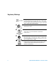
Regulatory Markings The CE mark is a registered trademark of the European Community.This CE mark shows that the product complies with all the relevant European Legal Directives. If it was accompanied by a year, it indicates the year the design was approved. This ISM device complies with Canadian ICES-001. The CSA mark is a registered trademark of the Canadian Standards Association. The UL mark is a registered trademark of Underwriters Laboratories Inc.
DECLARATION OF CONFORMITY According to ISO/IEC Guide 22 and CEN/CENELEC EN 45014 Generic example Manufacturer’s Name: Manufacturer’s Address: Agilent Technologies Microwave Products (M) Sdn.
Product Regulations EMC IEC 61326-1:1997+A1:1998 / EN 61326-1:1997+A1:1998 CISPR 11:1990 / EN 55011:1991 – Group 1 Class A IEC 61000-4-2:1995+A1:1998 / EN 61000-4-2:1995 (ESD 4kV CD, 8kV AD) IEC 61000-4-3:1995 / EN 61000-4-3:1995 (3V/m, 80% AM) IEC 61000-4-4:1995 / EN 61000-4-4:1995 (EFT 0.5kV lineline, 1kV line-earth) IEC 61000-4-5:1995 / EN 61000-4-5:1995 (Surge 0.5kV lineline, 1kV line-earth) IEC 61000-4-6:1996 / EN 61000-4-6:1996 (3V, 0.
Contents 1 Getting Started Tutorial 13 Introducing the Agilent U1251A and U1252A Handheld Digital Multimeter 14 Adjusting the Tilt-Stand 15 The Front Panel at a Glance 17 The Rotary Switch at a Glance 18 The Keypad at a Glance 19 The Display at a Glance 21 Selection of Display by Hz Button 25 Selection of Display by Dual Button 27 Selection of Display by SHIFT Button 30 The Terminals at a Glance 32 The Rear Panel at a Glance 33 2 Making Measurements 35 Measuring Voltage 36 Measuring Current 39 Measuring
Contents 10 3 Features and Functions 57 Dynamic Recording 58 Data Hold (Trigger Hold) 60 Refresh Hold 61 NULL (Relative) 63 Decibel Display 65 1 ms Peak Hold 67 Data Logging 69 Manual Logging 69 Interval Logging 71 Reviewing Logged Data 73 Square Wave Output (for U1252A) 75 Remote Communication 79 4 Changing The Default Setting 81 Selecting Setup Mode 82 Setting Data Logging Mode 86 Setting Thermocouple Types (for U1252A) 87 Setting Reference Impedance for dBm Measurement 88 Setting Minimum Frequency M
Contents Troubleshooting 115 6 Accessories 117 Checking the Shipping Contents 118 List of Accessories 119 7 Performance Tests and Calibration 121 Calibration Overview 122 Closed - case Electronic Calibration 122 Agilent Technologies Calibration Services 122 Calibration Interval 122 Adjustment is Recommended 123 Recommended Test Equipment 124 Basic Operating Test 125 Backlit Test 125 Testing the Display 125 Current Terminal Test 126 Charge Terminal Alert Test 127 Test Considerations 128 Input Connections
Contents U1252A AC+DC Specifications 161 Temperature and Capacitance Specifications 162 U1251A & U1252A Frequency Specifications(1) 163 Operating Specifications 166 General Specifications 167 12 Agilent U1251A/U1252A User’s and Service Guide
Agilent U1251A and U1252A Handheld Digital Multimeter User’s and Service Guide 1 Getting Started Tutorial Introducing the Agilent U1251A and U1252A Handheld Digital Multimeter 14 Adjusting the Tilt-Stand 15 The Front Panel at a Glance 17 The Rotary Switch at a Glance 18 The Keypad at a Glance 19 The Display at a Glance 21 Selection of Display by Hz Button 25 Selection of Display by Dual Button 27 Selection of Display by SHIFT Button 30 The Terminals at a Glance 32 The Rear Panel at a Glance 33 This chapte
1 Getting Started Tutorial Introducing the Agilent U1251A and U1252A Handheld Digital Multimeter The handheld digital multimeters’ key features are: • DC, AC and AC + DC (only U1252A) voltage and current measurements.
Getting Started Tutorial 1 • 50,000 count precision true RMS digital multimeter, designed to meet EN/IEC 61010- 1:2001 Category III 1000 V Overvoltage Protection, Pollution Degree II standards Adjusting the Tilt-Stand To adjust the meter to a 60° standing position, pull the tilt- stand outwards to its maximum reach.
Getting Started Tutorial 1 To adjust the meter to a hanging position, flip the stand upwards and over its maximum reach until it is detached from its hinge. Then flip the stand over so that the stand’s inner surface is facing the meter’s rear. Now, press the stand down into its hinge. Follow the step by step pictorial instructions below.
Getting Started Tutorial 1 The Front Panel at a Glance Display Keypad Rotary switch Terminals Agilent U1251A/U1252A User’s and Service Guide 17
1 Getting Started Tutorial The Rotary Switch at a Glance 4 5 6 7 3 8 2 9 1 10 Legend: No.
Getting Started Tutorial 1 The Keypad at a Glance The operation of each key is shown below. Pressing a key illuminates a related symbol on the display and sounds the beeper. Turning the rotary switch to another position resets the current operation of the key. Figure 1 shows the keypad of the U1252A. The ms% (Pulse width/Duty cycle), Hz , and frequency counter functions are only available on the U1252A.
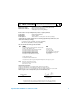
1 Getting Started Tutorial Function when pushed for less than 1 second Function when pushed for more than 1 second 4 scrolls through measuring function(s) at a particular rotary switch position. enters Log Review mode. Push to switch to manual or interval logging data. Push or to view first or last logged data respectively. Push or to scroll up or down logged data. Push for more than 1 second to exit mode.
Getting Started Tutorial 1 The Display at a Glance To view the full display (with all segments illuminated), push button and hold while turning the rotary switch from OFF to any non- OFF position. After you are done viewing the full display, push any button to resume normal functionality based on the rotary switch position. This is followed by a wake- up feature. The meter will then enter power save mode once auto power off (APF) is enable.
1 Getting Started Tutorial LCD Sign Description Remote control Thermocouple types: NULL (K-type) (J-type) Null math function Diode / Audible continuity Audible continuity for resistance View mode for checking logged data Data logging indication Square wave output (only U1252A) • Positive slope for pulse width (ms) and duty cycle (%) measurement • Charging capacitor as capacitance measurement • Negative slope for pulse width (ms) and duty cycle (%) measurement • Discharging capacitor as capaci
Getting Started Tutorial 1 The primary display signs are described below.
1 Getting Started Tutorial The secondary display signs are described below.
Getting Started Tutorial 1 The “+” or “–” sign is indicated when the positive or negative value has been measured or calculated. Each segment represents 2500 or 500 counts depending on the range indicated on the peak bar graph. See the table below.
1 Getting Started Tutorial measurement mode for current or voltage measurements — voltage or current on secondary display and frequency on primary display. Alternatively, pulse width (ms) or duty cycle (%) can appear on the primary display by pushing again. This allows simultaneous monitoring of real- time voltage or current with frequency, duty cycle or pulse width. Voltage or current resumes on primary display after you push and hold for more than 1 second.
Getting Started Tutorial Frequency (Hz) (DC current) 1 DC µA Pulse width (ms) Duty cycle (%) Frequency (Hz) (AC + DC current) [for U1252A] Pulse width (ms) Duty cycle (%) Frequency (Hz) (AC current) AC + DC µA AC mA or A Pulse width (ms) Duty cycle (%) Frequency (Hz) (DC current) DC mA or A Pulse width (ms) Duty cycle (%) Frequency (Hz) (AC + DC current) [for U1252A] Pulse width (ms) Hz (Frequency counter) - push Frequency (Hz) to select frequency division by 1 [for U1252A] Pulse width (m
1 Getting Started Tutorial Rotary switch position Primary display Secondary display AC V Hz (AC coupling) dBm or dBV (select by pushing .........
Getting Started Tutorial (AC + DC voltage) [for U1252A] AC + DC mV Hz (AC coupling) dBm or dBV AC + DC mV AC + DC mV AC mV AC + DC mV DC mV AC + DC mV Ambient temperature °C or °F DC μA Hz (DC coupling) DC μA AC μA DC μA Ambient temperature °C or °F AC μA Hz (AC coupling) AC μA DC μA AC μA Ambient temperature °C or °F AC + DC μA Hz (AC coupling) AC + DC μA AC μA AC + DC μA DC μA AC + DC μA Ambient temperature °C or °F DC mA Hz (DC coupling) DC mA AC mA %(0–20 or 4–20) DC
1 Getting Started Tutorial (AC + DC current) [for U1252A] AC A Ambient temperature °C or °F AC + DC A Hz (AC coupling) AC + DC A AC A AC + DC A DC A AC + DC A Ambient temperature °C or °F nF / V / Ω / nS (Capacitance) (Diode)/ Ambient temperature °C or °F Ω (Resistance)/ nS (Conductance) TEMP (Temperature) °C (°F) Ambient temperature °C or °F °C (°F) Ambient temperature °C or °F / 0°C compensation (select by pushing d) Selection of Display by SHIFT Button Table below shows selection of
Getting Started Tutorial 1 Ω Ω Ω nS Diode Hz Capacitance Temperature / TEMP DC μA AC μA Square wave output for AC + DC μA [for U1252A] DC mA AC mA AC + DC mA %(0–20 or 4–20) DC A AC A AC + DC A [for U1252A] Duty cycle (%) Pulse width (ms) U1252A N O TE 1. Push Push only. Agilent U1251A/U1252A User’s and Service Guide to switch between dBm and dBV measurement.
1 Getting Started Tutorial The Terminals at a Glance WARN IN G To avoid damaging this device, do not exceed the input limit. Figure 2 Table 2 U1252A Connector terminals Terminal connections for different measuring functions Rotary switch position Input terminal V . mV . Ω . Overload protection COM 1000 V R.M.S., for U1252A V for U1251A .TEMP 1000 V R.M.S. for short circuit <0.3 A Ω for U1252A μA .
Getting Started Tutorial 1 The Rear Panel at a Glance IR communication port Test probe holders Battery access cover Figure 3 Rear panel of U1252A Agilent U1251A/U1252A User’s and Service Guide 33
1 34 Getting Started Tutorial Agilent U1251A/U1252A User’s and Service Guide
Agilent U1251A and U1252A Handheld Digital Multimeter User’s and Service Guide 2 Making Measurements Measuring Voltage 36 Measuring AC voltage 36 Measuring DC voltage 38 Measuring Current 39 μA & mA Measurement 39 % Scale of 4–20 mA 40 A measurement 41 Frequency Counter 42 Measuring Resistance, Conductance and Testing Continuity 44 Testing Diodes 48 Measuring Temperature 52 Alerts and Warning During Measurement 55 Overload Alert 55 Input Warning 55 Charge Terminal Alert 56 This chapter contains the detail
2 Making Measurements Measuring Voltage The meter offers true- RMS readings for AC measurements that are accurate for sine waves, square waves, triangle waves, staircase waves and other waveforms without any DC offset. For AC with DC offset, use AC + DC measurement on or rotary switch location. This applies only to U1252A. WARN IN G Ensure that terminal connections are correct for that particular measurement before any measurement. To avoid damaging the device, do not exceed the input limit.
Making Measurements 2 MAX Figure 3 Measuring AC voltage Agilent U1251A/U1252A User’s and Service Guide 37
2 Making Measurements MAX Figure 4 Measuring DC voltage Measuring DC voltage 1 Set the rotary switch to and . 2 Connect the red and black test leads to input terminals V.mV and COM respectively. 3 Probe the test points and read the display.
Making Measurements 2 Measuring Current μA & mA Measurement 1 Set the rotary switch to . 2 Connect the red and black test leads to input terminals μA.mA and COM respectively. 3 Probe the test points in series with the circuit, and read the display.
2 Making Measurements % Scale of 4–20 mA The % scale for 4–20 mA or 0–20 mA is calculated using its corresponding DC mA measurement. Meter will optimize the best resolution automatically as per the below table. The and bar graph is used for ranging 50 mA and 500 mA. The % scale for 4–20 mA or 0–20 mA is set to two ranges as follows: % (0–20 or 4–20 mA) Always auto range 999.99% DC mA Auto or manual range 50 mA, 500 mA 9999.
Making Measurements 2 A measurement 1 Set the rotary switch to . 2 Connect the red and black test leads to 10A input terminal A and COM respectively. The meter is set to A measurement automatically when the red test lead is plugged into the A terminal.
2 Making Measurements Frequency Counter WARN IN G Use the frequency counter for low voltage application. Never use the frequency counter on line power system. Hz 1 Set the rotary switch to . 2 Push to select the Frequency counter (Hz) function. “- 1- “ on the secondary display means the input signal frequency is divided by 1. This accommodates for higher frequency range of up to 2 MHz. 3 Connect the red and black test leads to input terminals V and COM respectively.
Making Measurements 2 Push MAX Figure 8 Measuring frequency Agilent U1251A/U1252A User’s and Service Guide 43
2 Making Measurements Measuring Resistance, Conductance and Testing Continuity CAU T ION Disconnect circuit power and discharge all high-voltage capacitors before measuring resistance to prevent possible damage to the meter or the device under test. 1 Set the rotary switch to Ω nS. 2 Connect the red and black test leads to input terminals Ω and COM respectively. 3 Probe the test points (by shunting the resistor) and read the display.
Making Measurements 2 4 Push to scroll through audible continuity, conductance and resistance tests as shown in Figure 10. Audible continuity Figure 10 Audible continuity, conductance and resistance test.
2 Making Measurements In the range of 0–500 Ω, the beeper will sound if the resistance value falls below 10 Ω. For other ranges, the beeper will sound if the resistance falls below the typical values indicated in the table below. Measuring range Beeper sounds when 500.00 Ω < 10 Ω 5.0000 kΩ < 100 Ω 50.000 kΩ < 1 kΩ 500.00 kΩ < 10 kΩ 5.0000 MΩ < 100 kΩ 50.000 MΩ < 1 MΩ 500.00 MΩ < 10 MΩ Conductance measurement eases measurement of very high resistance of up to 100 GΩ.
Making Measurements 2 MAX Figure 11 Conductance measurement Agilent U1251A/U1252A User’s and Service Guide 47
2 Making Measurements Testing Diodes CAU T ION Disconnect circuit power and discharge all high-voltage capacitors before testing diodes to prevent possible damage to the meter. To test a diode, turn the circuit power off, and remove the diode from the circuit. After that, proceed as follows: 1 Set the rotary switch to . 2 Connect the red and black test leads to input terminals and COM respectively.
Making Measurements 2 MAX Figure 12 Measuring forward bias of diode Agilent U1251A/U1252A User’s and Service Guide 49
2 Making Measurements .
Making Measurements 2 Measuring Capacitance CAU T ION Disconnect circuit power and discharge all high-voltage capacitors before measuring capacitance to prevent possible damage to the meter or the device under test. To confirm that capacitors have discharged, use the DC voltage function. The meter measures capacitance by charging the capacitor with a known current for a period of time, measuring the voltage and then calculating the capacitance. Larger the capacitors, longer the charging time.
2 Making Measurements Measuring Temperature CAU T ION Do not bend the thermocouple leads at sharp angles. Repeated bending over a period of time can break leads. The bead type thermocouple probe is suitable for making temperature measurements between –20 °C to 200 °C in Teflon compatible environments. Above this temperature, probes may emit toxic gas. Do not immerse this thermocouple probe in liquids.
Making Measurements 2 3 Plug the thermocouple adapter (with the thermocouple probe connected to it) into input terminals TEMP and COM. 4 Touch the measurement surface with the thermocouple probe. 5 Read the display. If you are working in a varied environment, where ambient temperature is not constant, do the following: 1 Push to select 0 °C compensation. This allows a quick measurement of the relative temperature. 2 Avoid contact between the thermocouple probe and the measurement surface.
2 Making Measurements Press MAX Figure 14 Surface temperature measurement 54 Agilent U1251A/U1252A User’s and Service Guide
Making Measurements 2 Alerts and Warning During Measurement Overload Alert WARN IN G For your safety, please be aware of the alert. When you are alerted, just remove the test leads from the measuring source. The meter provides an overload alert for voltage measurement in both auto and manual range modes. The meter beeps periodically once the measuring voltage exceeds 1010 V. For your safety, please be aware of this alert.
2 Making Measurements Charge Terminal Alert The meter sounds an alerting beep when the terminal detects a voltage level of more than 5 V and the rotary switch is not set to the corresponding location. The primary display indicates a flashing “Ch.Err” until the lead is removed from input terminal. See Figure 16.
Agilent U1251A and U1252A Handheld Digital Multimeter User’s and Service Guide 3 Features and Functions Dynamic Recording 58 Data Hold (Trigger Hold) 60 Refresh Hold 61 NULL (Relative) 63 Decibel Display 65 1 ms Peak Hold 67 Data Logging 69 Manual Logging 69 Interval Logging 71 Reviewing Logged Data 73 Square Wave Output (for U1252A) 75 Remote Communication 79 This chapters contains detailed information on the features and functions that are available in this meter.
3 Features and Functions Dynamic Recording The Dynamic Recording mode can be used to detect intermittent turn on or turn off voltage or current surges and verify measuring performance without the user being present during that particular period of time. At the same time, you can take readings simultaneously while performing other task. The average reading is useful for smoothing out unstable inputs, estimating the percentage of time a circuit is operated, and verifying circuit performance.
Features and Functions or Push 3 for >1 s Push MAX MIN Push MAX MIN for >1 s or Push for >1 s Push MAX MIN Push MAX MIN for >1 s or Push for >1 s Figure 17 Dynamic recording mode operation Agilent U1251A/U1252A User’s and Service Guide 59
3 Features and Functions Data Hold (Trigger Hold) The data hold function allows operators to freeze the displayed digital value. 1 Push to freeze the displayed value and to enter manual trigger mode. TRIG is displayed. 2 Push to trigger the freeze of the next value being measured. TRIG flashes before the new value is updated onto the display. 3 Push and hold quit this mode.
Features and Functions 3 Refresh Hold The hold function allows operators to hold the displayed digital value. The bar- graph is not held, fix proportional to real measurement value. You can use the setup mode to enable the Refresh Hold when you are working on a difficult measuring field. This function will auto trigger or update Hold value with new measuring value, and sound a tone to remind user. Press button to enter Refresh Hold mode. The present value will be held, and the sign of will be lit.
Features and Functions 3 The HOLD sign flashes until the measured value is stable and updated Figure 19 Refresh hold mode operation N O TE • For voltage and current measurements, the holding value will not be updated if the reading is below 500 counts. • For resistance and diode measurements, the holding value will not be updated if the reading is in “OL” (open state). • The holding value may not be updated when the reading does not reach the stable state for all measurements.
Features and Functions 3 NULL (Relative) The NULL function subtracts a stored value from the present measurement and displays the difference between the two. 1 Push to store the displayed reading as the reference value to be subtracted from subsequent measurements and to set the display to zero. NULL is displayed. N O TE Null can be set for both auto and manual range setting, but not in the occurrence of an overload. 2 Push to see the stored reference value.
3 Features and Functions Figure 20 Null (relative) mode operation 64 Agilent U1251A/U1252A User’s and Service Guide
Features and Functions 3 Decibel Display The dBm operation calculates the power delivered to a reference resistance relative to 1 mW, and can be applied to DC V, AC V and AC + DC V measurements for decibel conversion. Voltage measurement is converted to dBm by using the following formula: The reference resistance may be selected from 1~9999Ω in Setup mode. Default value is 50Ω. The decibel of voltage is calculated with respect to 1 V.
3 Features and Functions Figure 21 dBm/dBV display mode operation 66 Agilent U1251A/U1252A User’s and Service Guide
Features and Functions 3 1 ms Peak Hold This function allows the measurement of half- cycle peak voltage for analysis of components such as power distribution transformers and power factor correction capacitors. The peak voltage obtained can be used to determine the crest factor: Crest factor = Peak value/True RMS value 1 Push for more than 1 second to toggle 1 ms Peak Hold mode ON / OFF. 2 Push to scroll through maximum and minimum peak readings.
3 Features and Functions Figure 22 1 ms peak hold mode operation 68 Agilent U1251A/U1252A User’s and Service Guide
Features and Functions 3 Data Logging Data logging function eases recording of test data for future review or analysis. Since data is stored in non- volatile memory, the data remains saved when the meter is turned OFF or battery is being changed. The two options offered are hand (manual) logging and interval (automatic) logging functions. Data logging records the value on primary display only. Manual Logging Hand (Manual) logging can be specified in Setup mode.
3 Features and Functions Figure 23 Hand (Manual) logging mode operation N O TE Maximum data that can be stored is 100 entries. When the 100 entries are filled, “FULL” is indicated on the secondary display, as shown in Figure 24. Figure 24 Full Log 3 Push 70 for more than 1 second to exit this mode.
Features and Functions 3 Interval Logging Interval (automatic) logging mode can be specified in Setup mode. 1 Push for more than 1 second to store the present value and function on primary display to memory. and the logging index are indicated. The reading automatically logs into the memory by every interval set in Setup mode. N O TE The maximum data that can be stored is 200 entries. When the 200 entries are filled, “FULL” is indicated on the secondary display.
3 Features and Functions Figure 25 Interval (Automatic) logging mode operation 72 Agilent U1251A/U1252A User’s and Service Guide
Features and Functions 3 Reviewing Logged Data 1 Push for more than 1 second to enter Log Review mode. Last recorded entry and last logging index are displayed. 2 Push to switch between hand (manual) and interval (automatic) logging review mode. 3 Push to ascend or to descend through logged data. Press to select first record and press to select the last record for quick navigation. 4 Push for more than 1 second at the respective Log Review mode to clear logged data.
3 Features and Functions Figure 26 Log review mode operation 74 Agilent U1251A/U1252A User’s and Service Guide
Features and Functions 3 Square Wave Output (for U1252A) Square wave output is a unique function for many applications, such as PWM (Pulse Width Modulation) output, adjustable voltage control, and synchronic clock (baud rate generator). You can also use this function to check and calibrate flow- meter displays, counters, tachometers, oscilloscopes, frequency converter, frequency transmitter and other frequency input devices. 1 Turn the rotary switch to position.
3 Features and Functions Push Figure 27 Frequency adjustment for square wave output 5 Push to select pulse width (%) on primary display. 6 Push or to adjust the pulse width. The pulse width can be set for 256 steps and each step is 1/ (256 x Frequency). The display range auto- adjusts in the range of 9.9999~9999.9 ms.
Features and Functions 3 Figure 28 Duty cycle adjustment for square wave output Agilent U1251A/U1252A User’s and Service Guide 77
3 78 Features and Functions Agilent U1251A/U1252A User’s and Service Guide
Features and Functions 3 Figure 29 Pulse width adjustment for Square Wave Agilent U1251A/U1252A User’s and Service Guide 79
3 Features and Functions Remote Communication The meter has a bi- directional (full duplex) communication capability that eases data storing from the meter to PC. The necessary accessory for this is the optional USB- RS232 together with the application software in the accompanying CD. Refer to the “Agilent GUI Software Helpfile” in the CD for instructions on how to perform the PC- meter remote communication.
Features and Functions 3 To PC USB Figure 30 Cable Connection for remote communication Agilent U1251A/U1252A User’s and Service Guide 81
Agilent U1251A and U1252A Handheld Digital Multimeter User’s and Service Guide 4 Changing The Default Setting Selecting Setup Mode 82 Setting Data Logging Mode 86 Setting Thermocouple Types (for U1252A) 87 Setting Reference Impedance for dBm Measurement 88 Setting Minimum Frequency Measurement 89 Setting Temperature Unit 90 Setting Auto Power Saving Mode 92 Setting % Scale Readout 94 Setting Beep Frequency 95 Setting Backlit Timer 96 Setting Baud Rate 97 Setting Parity Check 98 Setting Data Bit 99 Setting
4 Changing The Default Setting Selecting Setup Mode To enter Setup mode, perform the following steps: 1. Turn meter OFF. 2. From OFF position, push and hold while turning the rotary switch to any non- OFF position. N O TE When you hear a beep, the meter is in Setup mode and you can release To change a menu item setting in Setup mode, perform the following steps : 1. Push or to scroll through menu items. 2. Push or to scroll through available settings.
Changing The Default Setting Table 3 Available setting options in Setup mode Menu item Available setting options Display Description Display rHoLd(1) Refresh Hold OFF d-LoG Data logging Hand 1–9999 s t.
4 Changing The Default Setting Print ON, OFF Print Available setting options Menu item Display rESEt Enables auto send of data to PC continuously when set to ON tEMP Default factory setting Description Display Description Reset dEFAU Enables reset of factory settings by pushing and holding Temperature(4) d-CF OFF dEFAU for more than 1 second Sets temperature measurement to °C but pushing d-CF swaps display to °F d-F Sets temperature measurement to °F d-FC Sets temperature measureme
Changing The Default Setting 4 Setting Data Hold/Refresh Hold Mode 1. Set OFF to enable Data Hold mode (manual trigger by key or bus via remote control). 2. Set variation count within 100~1000 range to enable Refresh Hold mode (automatic trigger). When the variation of measuring value exceeds the setting of variation count, the Refresh Hold will be ready to trigger.
4 Changing The Default Setting Setting Data Logging Mode 1. Set “Hand” to enable hand (manual) data logging mode. 2. Set interval within 0001~9999 seconds to enable interval (automatic) data logging mode. 3. Push or to switch between manual and interval data logging setup.
Changing The Default Setting 4 Setting Thermocouple Types (for U1252A) The types of thermocouple sensor that can be selected are J and K types. Default type is K type. Push or to switch between J and K type.
4 Changing The Default Setting Setting Reference Impedance for dBm Measurement The reference impedance can be set from 1 to 9999 default value is 50 W. W .
Changing The Default Setting 4 Setting Minimum Frequency Measurement The minimum frequency setup influences the measuring rates for frequency, duty cycle, and pulse width. Typical measuring rate defined at the general specification is based on the minimum frequency of 1 Hz.
4 Changing The Default Setting Setting Temperature Unit Four combination displays are available: • Celsius only (°C on primary display) single display setting • Celsius- Fahrenheit (d- CF) and Fahrenheit- Celsius (d- FC) dual display setting. N O TE Primary-Secondary Display can be swapped by pushing • Fahrenheit only (°F on primary display) single display setting.
Changing The Default Setting 4 Figure 36 Temperature unit setup Agilent U1251A/U1252A User’s and Service Guide 91
4 Changing The Default Setting Setting Auto Power Saving Mode • The timer for APF (Auto Power OFF) can be set for the range of 1~99 minutes. To activate the meter after it has auto power off, turn the rotary switch to the OFF position, then turn it back on again. • “OFF” means disables APF. is indicated on the display during subsequent measurements.
Changing The Default Setting Figure 37 Agilent U1251A/U1252A User’s and Service Guide 4 Auto power saving setup 93
4 Changing The Default Setting Setting % Scale Readout This setting converts the DC current measuring display to % scale readout — 4- 20 mA or 0- 20 mA as proportional to 0~100%. The 25% scale readout represents DC 8 mA at 4- 20 mA and DC 5 mA at 0- 20 mA.
Changing The Default Setting 4 Setting Beep Frequency • The driving frequency can be set to 2400, 1200, 600 or 300 Hz. “OFF” disables beep.
4 Changing The Default Setting Setting Backlit Timer • Timer can be set to 1~99 seconds. Backlit turns off automatically after the set period. • “0FF” disables turning off backlit automatically.
Changing The Default Setting 4 Setting Baud Rate The baud rate is selected for remote control. The available settings are 2400, 4800, 9600 and 19200 Hz.
4 Changing The Default Setting Setting Parity Check The parity check is selected for remote control. It can be set to either none, even or odd bit.
Changing The Default Setting 4 Setting Data Bit Data bit is selected for remote control. It can be set to either 8 or 7 bits.
4 Changing The Default Setting Setting Echo Mode • Echo ON enables return of characters to PC in remote communication. • Echo OFF disables Echo mode.
Changing The Default Setting 4 Setting Print Mode Print ON enables print out of measured data to PC when measuring cycle is completed. In this mode, the meter automatically sends the newest data to the host continuously but does not accept any commands from the host. flashes during Print operation.
4 Changing The Default Setting Returning to Default Factory Settings • Push for more than 1 second to reset to default factory settings except the Temperature setting. • The Reset menu item automatically reverts to Refresh Hold menu item after reset has taken place.
Agilent U1251A and U1252A Handheld Digital Multimeter User’s and Service Guide 5 Maintenance Introduction 104 General Maintenance 104 Battery Replacement 105 Charging Battery 106 Fuse Replacement 113 Troubleshooting 115 This chapter will help you troubleshoot a failing handheld digital multimeter.
5 Maintenance Introduction Repair or service which are not covered in this manual should only be performed by qualified personnel. General Maintenance WARN IN G Ensure that terminal connections are correct for that particular measurement before any measurement. To avoid damaging the device, do not exceed the input limit. Besides the above hazard, dirt or moisture in the terminals can distort readings. Cleaning steps are as follows: 1 Turn the meter off and remove the test leads.
Maintenance 5 Battery Replacement WARN IN G Never discharge the battery by shorting it or reverse polarity in any subjects. Make sure the battery is rechargeable before charging it. Never rotate the rotary switch under charging as DC 24V has been applied to charging terminals. The meter is powered by 7.2 V battery, and use only specified battery. To ensure the specification specified, it is suggested to replace battery immediately when the sign of low battery is displayed and flashing.
5 Maintenance 2 Slide down and the battery cover. 3 Lift the battery cover up. 4 Replace the specified battery. 5 Reverse the procedure of opening the cover to close the bottom cover. Charging Battery WARN IN G Never discharge the battery by shorting it or reverse polarity in any subjects. Make sure the battery is rechargeable before charging it. Never rotate the rotary switch under charging as DC 24V has been applied to charging terminals.
Maintenance 5 4 The primary display will indicate “bAt” and the ‘SbY” is flashing on the second display and short tone sounds to remind you whether to charge battery or not. Press SHIFT button to start charging the battery, or the meter will automatically start the self- test after 24V supply is applied. It is recommended not to charge the battery if the battery capacity is over 90%. Condition Battery Voltage Proportional Percentage Trickle (SBY) 6.0 V ~ 8.2 V 0% ~ 100% Under charging 7.2 V ~ 10.
5 Maintenance 5 After pushing the SHIFT button or self- start, the meter will do a self- test to check if the battery inside the meter is a rechargeable battery or not. The self- test will take about 2- 3 minutes. Avoid from operating any push buttons during the self- test. An error message is diplayed shown below.
Maintenance Error Condition 5 Secondary Display OL • No battery in the meter • Battery failing • Battery is full C-Err • No rechargeable battery inside • Battery failing Figure 49 Error messages Agilent U1251A/U1252A User’s and Service Guide 109
5 Maintenance N O TE • • If OL message occurs while the battery is inside, please do not charge the battery. • If C-Err message occurs, check if the battery is the specified type. We specified the correct battery in this guide. Please make sure that the battery is the specified rechargeable battery before charging it again. After replacing with the specified rechargeable battery, press SHIFT button to redo the self-test.
Maintenance 5 7. The charge end message (C–End) will be displayed on the secondary display once charging is completed. The trickle charging current will be provided to maintain the battery and capacity. The flashing signs of displayed to show the trickle state. will be 8. Remove the DC adapter when the C–End is displayed on the secondary display. Do not turn the rotary switch before removing the adapter from the terminals.
5 Maintenance Figure 52 112 Battery charging procedures Agilent U1251A/U1252A User’s and Service Guide
Maintenance 5 Fuse Replacement N O TE This manual provides only the fuse replacement procedures, but not the fuse replacement markings. The following procedures will assist you to replace the fuse of the meter. 1 Turn the meter off and disconnect the test leads from external equipment. Make sure the adaptor is removed. 2 Use clean/dry gloves on your hands and do not touch any components except the fuse and plastic parts.
5 Maintenance Fuse 1 Fuse 2 Figure 53 Fuse replacement 114 Agilent U1251A/U1252A User’s and Service Guide
Maintenance 5 Troubleshooting WARN IN G To avoid electrical shock, do not perform any service unless you are qualified to do so. If the instrument fails to operate, check the battery and test leads. Replace them if necessary. And if the instrument still doesn’t function, check the operating procedure in this instruction manual. When servicing, Use specified replacement parts only. The table below will assist you to identify some basic problems.
5 116 Maintenance Agilent U1251A/U1252A User’s and Service Guide
Agilent U1251A and U1252A Handheld Digital Multimeter User’s and Service Guide 6 Accessories Checking the Shipping Contents 118 List of Accessories 119 This chapter contains information on the standard and optional accessories. It includes the shipping contents along with this instrument.
6 Accessories Checking the Shipping Contents Verify that you have received the following items with your multimeter: • Soft carrying case • 9 V alkaline battery • Rechargeable 7.2 V battery (for U1252A only) • Power cord & AC adapter (for U1252A only) • Standard Test Lead Kit • Quick Start Guide • CD containing the User’s Guide, application software and instrument drivers • Certificate of Calibration If anything is missing, contact your nearest Agilent Sales Office.
Accessories 6 List of Accessories Type Model ID Description Soft Carrying Case U1251A U1252A x x x Rechargeable 7.
6 120 Accessories Agilent U1251A/U1252A User’s and Service Guide
Agilent U1251A and U1252A Handheld Digital Multimeter User’s and Service Guide 7 Performance Tests and Calibration Calibration Overview 122 Recommended Test Equipment 124 Basic Operating Test 125 Test Considerations 128 Performance Verification Tests 130 Calibration Security 138 Calibration Process 142 Adjustments Consideration 144 This chapter contains performance test procedures and adjustment procedures.
7 Performance Tests and Calibration Calibration Overview This manual contains procedures for verification of the instrument’s performance and adjustment (calibration). N O TE Make sure you have read “Test Considerations” on page 128 before calibrating the instrument. Closed - case Electronic Calibration The instruments features closed- case electronic calibration. No internal mechanical adjustments are required. The instrument calculates correction factors based upon the input reference value you set.
Performance Tests and Calibration 7 warranted beyond the 1- year calibration interval. Agilent does not recommend extending calibration intervals beyond 2 years for any application. Adjustment is Recommended Specifications are only guaranteed within the period stated from the last adjustment. Whatever calibration interval you select, Agilent recommends that complete re- adjustment should always be performed at the calibration interval.
7 Performance Tests and Calibration Recommended Test Equipment The test equipment recommended for the performance verification and adjustment procedures is listed below. If the exact instrument is not available, substitute calibration standards of equivalent accuracy. A suggested alternative method would be to use the Agilent 3458A 8½ - Digit Digital Multimeter to measure less accurate yet stable sources.
Performance Tests and Calibration 7 Basic Operating Test Basic Operating Test is to test the basic operability of the instrument. Repair is required if the instrument fails the Basic Operating Test. Backlit Test Press the BAT button to test the backlight. It will momentarily toggle backlit ON and OFF. Testing the Display Press the button and turn on the Meter to view all segments of the display. Compare the display with the example in Figure 1.
7 Performance Tests and Calibration Current Terminal Test This test determines if the input warning of the current terminal test is functioning properly. The meter sounds an alert beep when the test lead is inserted to A terminal but rotary switch is not set to mA.A function. The primary display will indicate “A- Err”. It is shown in Figure 55. The primary display will keep flashing unless the test lead is removed from “A” terminal.
Performance Tests and Calibration 7 Charge Terminal Alert Test This test determines if the charge terminal alert is operating properly. The meter sounds an alert when the terminal detects a voltage level of more than 5V but rotary switch is not set to position. The meter sounds an alert beep and primary display indicates and flashes “Ch.Err” until the lead is removed from Figure 56 N O TE terminal.
7 Performance Tests and Calibration Test Considerations Long test leads can also act as an antenna causing pick- up of AC signals. For optimum performance, all procedures should comply with the following recommendations: • Assure that the calibration ambient temperature is stable and between 18 °C and 28 °C. Ideally the calibration should be performed at 23 °C ± 1 °C. • Assure ambient relative humidity is less than 80%.
Performance Tests and Calibration 7 Input Connections Test connections to the instrument are best accomplished using the dual banana plug with copper wire short between two terminals for low- thermal offset measurement. Shielded, twisted- pair, Teflon interconnect cables of minimum length are recommended between the calibrator and the multimeter. Cable shields should be earth ground referenced. This configuration is recommended for optimal noises and settling time performance during calibration.
7 Performance Tests and Calibration Performance Verification Tests Use the Performance Verification Tests to verify the measurement performance of the instrument. The performance verification tests use the instrument’s specifications listed in the U1251A/U1252A Data Sheet. The performance verification tests are recommended as acceptance tests when you first receive the instrument. The acceptance test results should be compared against the 1 year test limits.
Perform the verification test steps in the following Table 5: Table 5 Verification Test Step Test Function Range 5520A Output Error from nominal 1 year U1251A 1 Turn the rotary switch to the 5V U1252A 5 V, 1 kHz ± 32.5 mV ± 22.5 mV 5 V, 10 kHz ± 52.5 mV ± 22.5 mV 5 V, 20 kHz N/A ± 41.5 mV 5 V, 30 kHz ± 84 mV N/A 5 V,100 kHz N/A ± 187mV 50 V,1 kHz ± 325 mV ± 225 mV 50 V,10 kHz ± 525 mV ± 225 mV 50 V, 20 kHz N/A ± 415 mV 50 V, 30 kHz ± 840 mV N/A 50 V, 100 kHz N/A ± 1.
7 Performance Tests and Calibration Step Test Function Range 5520A Output Error from nominal 1 year U1251A 4 Turn the rotary switch to U1252A 5V 5V ± 2 mV ±1.75 mV 50 V 50 V ± 20 mV ± 17.5 mV 500 V 500 V ± 200 mV ± 200 mV 1000 V 1000 V ± 800 mV ± 800 mV 5V 5 V,1 kHz N/A ± 22.5 mV 5 V, 10 kHz N/A ± 22.5 mV 5 V, 20 kHz N/A ± 41.5 mV 5 V, 100 kHz N/A ± 187 mV 50 V, 1 kHz N/A ± 225 mV 50 V, 10 kHz N/A ± 225 mV 50 V, 20 kHz N/A ± 415 mV 50 V, 100 kHz N/A ± 1.
Performance Tests and Calibration Step Test Function Range 5520A Output Error from nominal 1 year U1251A 6 Turn the rotary switch to the mV position 7 Press the button to go to mV mode [1] [2] U1252A ± 75 μV [2] 50 mV 50 mV ± 75 μV 500 mV 500 mV ± 0.2 mV ± 0.175 mV –500 mV ± 0.2 mV ± 0.175 mV 1000 mV ± 0.8 mV ± 0.75 mV –1000 mV ± 0.8 mV ± 0.75 mV 50 mV, 1 kHz ± 0.34 mV ± 0.24 mV 50 mV, 10 kHz ± 0.54 mV ± 0.39 mV 50 mV, 20 kHz N/A ± 0.415 mV 50 mV, 30 kHz ± 0.
7 Performance Tests and Calibration Step Test Function Range 5520A Output Error from nominal 1 year U1251A 8 Turn the rotary switch to the W position 9 Press mode button to go to ns 10 Turn the rotary switch to the Hz/ position (for model U1252A), to position (for model U1251A) U1252A 500 W 500 W ± 500 mW [3] ± 350 mW [3] 5 kW 5 kW ± 4.5 W [3] ± 3 W [3] 50 kW 50 kW ± 45 W ± 30 W 500 kW 500 kW ± 450 W ± 300 W 5 MW 5 MW ± 10.5 kW ± 8 kW 50 MW [4] 50 MW ± 0.510 MW ± 0.
Performance Tests and Calibration Step Test Function Range 5520A Output Error from nominal 1 year U1251A 14 15 16 Press button to go to TEMP mode[8] Turn the rotary swich to the uA position Press button to go to uA mode [1] 17 18 Turn the rotary switch to the mA.A position Press button to go to mA mode [1] U1252A 100.00 μF 100.00 μF ± 1.05 μF ± 1.05 μF 1000.0 μF 1000.0 μF ± 10.5 μF ± 10.5 μF 10.00 mF 10.00 mF ± 0.105 mF ± 0.105 mF 100.00 mF 10.00 mF ± 0.4 mF ± 0.
7 Performance Tests and Calibration Step Test Function Range 5520A Output Error from nominal 1 year U1251A 19 20 Press button to go to A mode Turn the rotary switch to the position Duty Cycle U1252A 5A 5 A, 1 kHz ± 42 mA ± 37 mA 3A 3 A, 5 kHz ± 96 mA ± 96 mA 10 A[11] 10 A, 1 kHz ± 100 mA ± 90 mA Square Wave Output Use 53131A 120 Hz @ 50% N/A ± 26 mHz 4800 Hz @ 50% N/A ± 260 mHz 100 Hz @ 50% N/A ± 0.398%[12] 100 Hz @ 25% N/A ± 0.398%[12] 100 Hz @ 75% N/A ± 0.
Performance Tests and Calibration 7 [1] The additional error to be added as frequency > 20 kHz and signal input < 10% of range: 300 counts of LSD per kHz. [2] The accuracy could be 0.05% + 10, always use relative function to zero thermal effect (short test leads) before measuring the signal. [3] The accuracy of 500 W and 5kW is specified after NULL function. [4] For range of 50 MW, the RH is specified for < 60%. [5] The accuracy is specified for < 50nS and after NULL function as open test lead.
7 Performance Tests and Calibration Calibration Security The calibration security code prevents accidental or unauthorized adjustments to the instrument. When you first receive your instrument, it is secured. Before you can adjust the instrument, you must unsecure it by entering the correct security code (see “Unsecuring the Instrument for Calibration” on page 139). The security code is set to 1234 when the instrument is shipped from the factory.
Performance Tests and Calibration 7 Unsecuring the Instrument for Calibration Before you can adjust the instrument, you must unsecure it by entering the correct security code. The security code is set to 1234 when the instrument is shipped from the factory. The security code is stored in non- volatile memory, and does not change when power has been off. To Unsecure the Instrument from the Front Panel 1 Turn the rotary switch to .
7 Performance Tests and Calibration To Change the Instrument Calibration Security Code from the Front Panel 1 When the instrument in the unsecured mode, press button for more than 1 second to enter Calibration Security Code setting mode. 2 The factory default calibration security code 1234 will be displayed on primary display. 3 Use the editing keys character in the code. 4 Use the the code.
Performance Tests and Calibration 7 To Unsecure the Instrument Without the Security Code To unsecure the instrument without the correct security code, follow the steps below. N O TE If you do not have a record of the security code, first try 1234 (the factory default code) through front panel or remote interface. 1 Record the last 4 digit serial numbers of the instrument. 2. Turn the rotary switch to 3. Press and . button simultaneously to enter the Calibration Security Code entry mode. 4.
7 Performance Tests and Calibration Now you can use 1234 as the security code. If want to enter a new security code, see “To Change the Instrument Calibration Security Code from the Front Panel” on page 140. Make sure you record the new security code. Calibration Process The following general procedure is the recommended method to complete a full instrument calibration. 1 Read “Test Considerations” on page 128. 2 Perform the verification tests to characterize the instrument (incoming data).
Performance Tests and Calibration 7 Using the Front Panel for Adjustments This section describes the process used to perform adjustments from the front panel. Selecting the Adjustment Mode Unsecure the instrument see “Unsecuring the Instrument for Calibration” on page 139 or “To Unsecure the Instrument Without the Security Code” on page 141. Once unsecured, the reference value will be indicated on the primary display.
7 Performance Tests and Calibration Adjustments Consideration You will need a test input cable and connectors set, and a Shorting Plug to adjust the instrument (see “Input Connections” on page 129). N O TE After each adjustment, the secondary display briefly shows PASS. If the calibration fails, the handheld multimeter sounds a beep, and an error number is shown in the secondary display. Calibration error messages are described on page 154.
Performance Tests and Calibration 7 Valid Adjustment Input Values Adjustment can be accomplished using the following input values below. Table 6 Function V Valid adjustment input values Range Valid Amplitude Input Values 5V, 50 V, 500 V, 1000 V 0.9 to 1.1 x Full Scale 5 V, 50 V, 500 V, 1000 V 0.9 to 1.1 x Full Scale 5 V, 50 V ,500 V, 1000 V 0.9 to 1.1 x Full Scale 50 mV, 500 mV, 1000 mV 0.9 to 1.1 x Full Scale 500 µA, 5000 µA 0.9 to 1.1 x Full Scale 50 mA, 440 mA, 5 A, 10 A 0.9 to 1.
7 Performance Tests and Calibration Adjustment Procedure Review the “Test Considerations” on page 128 and “Adjustments Consideration” on page 144 sections before beginning this procedure. 1 Turn the rotary switch to “Test Function” position, shown in the adjustment table. 2 After unsecuring the instrument, the instrument goes into the adjustment mode.
Performance Tests and Calibration 7 Successful completion of each adjustment value, the secondary display briefly showing PASS. An adjustment failure is sounded by a long beep and calibration error number appears in the secondary display. The primary display remains at the current Cal Item. Check the input value, range, function, and entered adjustment value to fix the problem and repeat the adjustment steps. 9 Repeat steps 1 through 8 for each adjustment point.
7 Performance Tests and Calibration Verify the adjustment with the following Table 6: Table 6 Adjustment table Step 1 Test Function Turn the rotary switch to the V position Cal Range U1252A 0.3 V,1 kHz 0.3000 V 0.3000 V 3 V, 1 kHz 3.0000 V 3.0000 V 3 V, 50 kHz N/A 3.0000 V 3 V, 1 kHz 03.000 V 03.000 V 30 V, 1 kHz 30.000 V 30.000 V 30 V, 50 kHz N/A 30.000 V 30 V,1 kHz 030.00 V 030.00 V 300 V,1 kHz 300.00 V 300.00 V 300 V, 50 kHz N/A 300.00 V 30 V, 1 kHz 0030.0 V 0030.
Performance Tests and Calibration Step 3 Test Function Press button to go to the V mode Cal Range U1252A 0.3 V, 1 kHz N/A 0.3000 V 3 V, 1 kHz N/A 3.0000 V 3 V, 50 kHz N/A 3.0000 V 3 V, 1 kHz N/A 03.000 V 30 V, 1 kHz N/A 30.000 V 30 V, 50 kHz N/A 30.000 V 30 V, 1 kHz N/A 030.00 V 300 V, 1 kHz N/A 300.00 V 300 V, 50 kHz N/A 300.00 V 30 V, 1 kHz N/A 0030.0 V 300 V, 1 kHz N/A 0300.0 V 300 V, 50 kHz N/A 0300.
7 Performance Tests and Calibration Step 5 Test Function Press button to go to the mV mode Cal Range U1252A 3 mV, 1 kHz 03.000 mV 03.000 mV 30 mV, 1 kHz 30.000 mV 30.000 mV 30 mV, 50 kHz N/A 30.000 mV 30 mV, 1 kHz 030.00 mV 030.00 mV 300 mV, 1 kHz 300.00 mV 300.00 mV 300 mV, 50 kHz N/A 300.00 mV 30 mV, 1 kHz 0030.0 mV 0030.0 mV 1000 mV, 1 kHz 1000.0 mV 1000.0 mV 1000 mV, 50 kHz N/A 1000.
Performance Tests and Calibration Step 7 Test Function Turn the rotary switch to the TEMP/ position Cal Range Input Cal Item U1251A U1252A Open Input terminal open (Remove any test leads and Short Plugs from the input terminal) oPEn oPEn 10 nF 3 nF 03.000 nF 03.000 nF 10 nF 10.000 nF 10.000 nF 10 nF 010.00 nF 010.00 nF 100 nF 100.00 nF 100.00 nF 100 nF 0100.0 nF 0100.0 nF 1000 nF 1000.0 nF 1000.0 nF 10 mF 10 mF 10.000 mF 10.000 mF 100 mF 100 mF 100.00 mF 100.
7 Performance Tests and Calibration 10 Press button to go to 500 mA 30 mA,1 kHz 030.00 mA 030.00 mA 300 mA,1 kHz 300.00 uA 300.00 mA 300 mA,1 kHz 0300.0 mA 0300.0 mA 3000 mA, 1 kHz 3000.0 mA 3000.0 mA Open Input terminal open (Remove any test leads and Short Plugs from the input terminal) oPEn oPEn 50 mA 30 mA 30.000 mA 30.000 mA 440 mA 300 mA 300.00 mA 300.00 mA mA mode 5000 mA 11 Turn the Rotary Switch to the mA.A position Move the test lead from uA.
Performance Tests and Calibration 7 Finishing the Adjustment 1 Remove all shorting plugs and connectors from the instrument. 2 Record the new Calibration Count. 3 Press and button simultaneously to exit the Adjustment Mode. Power off and on again. The instrument will then be secure. To Read the Calibration Count You can query the instrument to determine how many calibrations have been performed. N O TE Your instrument was calibrated before it left the factory.
7 Performance Tests and Calibration Calibration Errors The following errors indicate failures that may occur during a calibration.
Agilent U1251A and U1252A Handheld Digital Multimeter User’s and Service Guide 8 Specifications DC Specifications 157 U1251A AC Specifications 159 U1252A AC Specifications 160 U1252A AC+DC Specifications 161 Temperature and Capacitance Specifications 162 U1251A & U1252A Frequency Specifications(1) 163 Operating Specifications 166 General Specifications 167 This chapter describes the handheld digital multimeter’s specifications.
8 Specifications These specifications apply when using the U1251A and U1252A handheld digital multimeter in an environment that is free of electromagnetic interference and electrostatic charge. When using the multimeter in an environment where electromagnetic interference or significant electrostatic charge is present, measurement accuracy may be reduced.
Specifications 8 DC Specifications Table 5 Function Voltage(1) Resistance Range 50.000 mV Resolution 0.001 mV Test Current/ Burden Voltage - 500.00 mV 1000.0 mV 5.0000 V 50.000 V 500.00 V 1000.0 V 0.01 mV 0.1 mV 0.0001 V 0.001 V 0.01 V 0.1 V 0.01 Ω 1.04 mA 0.0001 kΩ 416 μA 50.000 MΩ(4) 0.001 kΩ 0.01 kΩ 0.0001 MΩ 0.001 MΩ 41.2 μA 4.12 μA 375 nA 187 nA 500.00 MΩ(4) 0.01 MΩ 500.00 nS(5) 500.00 μA 5000.0 μA 500.00 Ω(3) Diode Test Accuracy U1251A U1252A 0.05+50(2) 0.05+50(2) 0.025+5 0.
8 Specifications [1] Input impedance: >1GΩ for 50 mV to 1000 mV ranges. For U1251A, input impedance is 10 MΩ (nominal) for 5 V to 1000 V ranges. For U1252A, input impedance is 10 MΩ (nominal) in parallel with 1.1 MΩ at dual display. [2] The accuracy could be 0.05 %+10 for U1251A and 0.05 %+5 for U1252A. Always use NULL function to zero out the thermal effect before measuring the signal.
Specifications 8 U1251A AC Specifications Table 6 U1251A AC Accuracy ± (% of reading + No. of Least Significant Digit) Function True RMS AC Voltage (1) Function AC Current Range 50.000 mV 500.00 mV 1000.0 mV 5.0000 V 50.000 V 500.00 V Resolution 0.001 mV 0.01 mV 0.1 mV 0.0001 V 0.001 V 0.01 V 1000.0 V 0.1 V Range 30 Hz to 45 Hz 1+60 1+60 1+60 1+60 1+60 1+60 Frequency 45 Hz to 1 kHz 1 kHz to 10 kHz 0.6+40 1.0+40 0.6+25 1.0+40 0.6+25 1.0+25 0.6+25 1.0+25 0.6+25 1.0+25 0.6+25 1.0+25 1+60 0.6+40 1.
8 Specifications U1252A AC Specifications Table 7 U1252A AC Accuracy ± (% of reading + No. of Least Significant Digit) Frequency Function Range Resolution True RMS 50.000 mV 500.00 mV 1000.0 mV 5.0000 V 50.000 V 500.00 V 0.001 mV 0.01 mV 0.1 mV 0.0001 V 0.001 V 0.01 V AC Voltage (2) 1000.0 V 0.1 V 20 Hz – 45 Hz 1.5+60 1.5+60 1.5+60 1.5+60 1.5+60 1.5+60 1.5+60 45 Hz – 1 kHz 0.4+40 0.4+25 0.4+25 0.4+25 0.4+25 0.4+25 0.4+40 1 kHz – 10 kHz 0.7+40 0.4+25 0.4+25 0.4+25 0.4+25 0.
Specifications 8 U1252A AC+DC Specifications Table 8 U1252A AC Accuracy ± (% of reading + No. of Least Significant Digit) Frequency Function Range Resolution Voltage(2) 50.000 mV 500.00 mV 1000.0 mV 5.0000 V 50.000 V 500.00 V 0.001 mV 0.01 mV 0.1 mV 0.0001 V 0.001 V 0.01 V 1000.0 V Function Current 0.1 V Range 500.00 μA 30 Hz – 45 Hz 1.5+80 1.5+65 1.5+65 1.5+65 1.5+65 1.5+65 1.5+65 Resolution (4) 0.01 μA 0.1 μA 45 Hz – 1 kHz 0.4+60 0.4+30 0.4+30 0.4+30 0.4+30 0.4+30 0.
8 Specifications Temperature and Capacitance Specifications Function Thermocouple Type Range K -200 – 1372 °C/ -328 – 2502 °F -210 – 1200 °C/ -346 – 2192 °F Temperature(1) J(2) Function Range Resolution Resolution 0.1 °C/ 0.1 °F 0.1 °C/ 0.1 °F Accuracy ± (% of reading + Offset Capacitance 10.000 nF 100.00 nF 1000.0 nF 10.000 μF 100.00 μF 1000.0 μF 10.000 mF 100.00 mF Accuracy ± (% of reading + No. of 0.001 nF 0.01 nF 0.1 nF 0.001 μF 0.01 μF 0.1 μF 0.001 mF 0.
Specifications 8 U1251A & U1252A Frequency Specifications(1) Range Resolution Min. Input Frequency Accuracy ± (% of reading + No. of Least Significant Digit) 99.999 Hz 999.99 Hz 9.9999 kHz 99.999 kHz 999.99 kHz 0.001 Hz 0.01 Hz 0.0001 kHz 0.001 kHz 0.01 kHz 0.02%+3 <600 kHz 1 Hz U1251A Frequency Sensitivity During Voltage Measurement Input Range (Maximum input for specified accuracy = 10 x Range or 1000 V) 50.000 mV 500.00 mV 1000.0 mV 5.0000 V 50.000 V 500.00 V 1000.
8 Specifications U1251A & U1252A Frequency Sensitivity During Current Measurement Input Range Minimum Sensitivity (R.M.S. Sine-Wave) 20 Hz – 20 kHz 100 μA 250 μA 10 mA 25 mA 1A 2.5 A 500.00 μA 5000.0 μA 50.000 mA 440.00 mA 5.0000 A 10.000 A Duty Cycle(1) MODE RANGE ACCURACY AT FULL SCALE DC Coupling 0.01 % – 99.99 % 0.3 % per kHz + 0.3 % MODE RANGE ACCURACY AT FULL SCALE 500 ms 2000 ms 0.01 ms 0.1 ms 0.2 % + 3 0.
Specifications 8 Divide 100 (secondary display “-100-”) Range Resolution Accuracy ± (% of reading + No. of Least Significant Digit) Sensitivity Min. Input Frequency 9.9999 MHz 99.99 MHz 0.0001 MHz 0.001 MHz 0.002 %+5, <20 MHz 400 mV R.M.S. 600 mV R.M.S.
8 Specifications Operating Specifications Measuring rate 166 Function Times/second ACV 7 ACV + dB 7 DCV 7 ACV 7 AC + DC V 2 Ω/nS 14 Diode 14 Capacitance 4 (< 100 μF) DCI 7 ACI 7 AC + DC I 2 Temperature 6 Frequency 2 (>10 Hz) Duty cycle 1 (>10 Hz) Pulse width 1 (>10 Hz) Agilent U1251A/U1252A User’s and Service Guide
Specifications 8 General Specifications Display • Both primary and secondary displays are 5-digit liquid crystal display (LCD) with maximum reading of 50,000 counts. Automatic polarity indication.