Agilent U1241B and U1242B Handheld Digital Multimeters User’s and Service Guide Agilent Technologies
Notices © Agilent Technologies, Inc. 2009–2014 Warranty No part of this manual may be reproduced in any form or by any means (including electronic storage and retrieval or translation into a foreign language) without prior agreement and written consent from Agilent Technologies, Inc. as governed by United States and international copyright laws. The material contained in this document is provided “as is,” and is subject to being changed, without notice, in future editions.
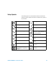
Safety Symbols The following symbols on the instrument and in the documentation indicate precautions which must be taken to maintain safe operation of the instrument. Direct current (DC) Off (supply) Alternating current (AC) On (supply) Both direct and alternating current Caution, risk of electric shock. Three-phase alternating current Caution, risk of danger (refer to this manual for specific Warning or Caution information). Earth (ground) terminal Caution, hot surface.
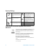
Regulatory Markings The CE mark is a registered trademark of the European Community.This CE mark shows that the product complies with all the relevant European Legal Directives. The C-tick mark is a registered trademark of the Spectrum Management Agency of Australia. This signifies compliance with the Australia EMC Framework regulations under the terms of the Radio Communication Act of 1992. ICES/NMB-001 indicates that this ISM device complies with Canadian ICES-001.
General Safety Information The following general safety precautions must be observed during all phases of operation, service and repair of this instrument. Failure to comply with these precautions or with specific warnings elsewhere in this manual violates safety standards of design, manufacture and intended use of the instrument. Agilent Technologies assumes no liability for the customer’s failure to comply with these requirements.
WA R N I N G • • • • • CAUTION VI Inspect the test probes for damaged insulation or exposed metal, and check for continuity. Do not use the test probe if it is damaged. Do not use repaired fuses or short-circuited fuse-holders. For continued protection against fire, replace the line fuses only with fuses of the same voltage and current rating and recommended type. Do not service or perform adjustments alone. Under certain conditions, hazardous voltages may exist, even with the equipment switched off.
Environment Conditions This instrument is designed for indoor use, in areas with low condensation and to be used with standard or compatible test probes.
Declaration of Conformity (DoC) The Declaration of Conformity (DoC) for this instrument is available on the Web site. You can search the DoC by its product model or description. http://regulations.corporate.agilent.com/DoC/search.htm NOTE VIII If you are unable to search for the respective DoC, please contact your local Agilent representative.
In This Guide… 1 Getting Started Chapter 1 introduces key features and steps to get started with a U1241B or U1242B handheld digital multimeter. This chapter also guides you through the basics of the front panel operations. 2 Features and Functions Chapter 2 contains the information on how to set up connections to perform multimeter measurements. It also describes the features and functions that are available in the U1241B and U1242B handheld digital multimeters in step-by-step instructions.
THIS PAGE HAS BEEN INTENTIONALLY LEFT BLANK.
Contents Contents 1 Getting Started 1 Introduction 2 Checking the Shipping Contents 3 The Front Panel at a Glance 4 Adjusting Tilt Stand 4 The Annunciator at a Glance 5 Analog Bar Graph 6 The Keypad and Rotary Switch at a Glance 6 The Input Terminal at a Glance 8 2 Features and Functions 9 Measuring Voltage 10 Measuring Current (> 440 mA) 10 Measuring Current (< 440 mA) 11 Measuring % Scale of 4 – 20 mA 11 Measuring Frequency 12 Measuring Resistance and Testing Continuity 12 Testing Diodes 13 Measuring
Contents XI 3 Default Setting Configurations 27 Setting Configurations 28 4 Service and Maintenance 31 General Maintenance 32 Battery Replacement 32 Fuse Replacement 33 Troubleshooting 35 Returning Instrument for Service 37 6 Performance Tests and Calibration 39 Calibration Overview 40 Closed-case Electronic Calibration 40 Calibration Interval 40 Adjustment is Recommended 41 Recommended Test Equipment 42 Basic Operating Test 43 Backlight Test 43 Testing the Display 43 Input-A Terminal Test 44 Input-m
Contents 6 Specifications and Characteristics 61 DC Specifications 62 AC Specifications 63 Resistance Specifications 64 Diode Check/Audible Continuity Test Specifications 64 Temperature Specifications 65 Capacitance Specifications 66 Harmonic Ratio Specifications 66 Frequency Specifications 67 Operating Specifications 68 General Characteristics 69 U1241B/U1242B User’s and Service Guide XII
Contents XIII U1241B/U1242B User’s and Service Guide
U1241B and U1242B Handheld Digital Multimeters User’s and Service Guide 1 Getting Started Introduction 2 Checking the Shipping Contents 3 The Front Panel at a Glance 4 Adjusting Tilt Stand 4 The Annunciator at a Glance 5 The Keypad and Rotary Switch at a Glance 6 The Input Terminal at a Glance 8 This chapter introduces key features and steps to get started with a U1241B or U1242B handheld digital multimeter. This chapter also guides you through the basics of the front panel operations.
1 Getting Started Introduction The handheld digital multimeters’ key features are: • DC, AC voltage and current measurements.
Getting Started 1 Checking the Shipping Contents Verify that you have received the following items for the standard shipped items or optional accessories that you may have ordered. If any of the above item missing, or any mechanical damage and defect on the multimeter, notify your nearest Agilent Technologies Sales Office. Table 1-1 List of standard items and optional accessories Type Model ID Standard Items U1241B or U1242B handheld digital multimeter Four 1.
1 Getting Started The Front Panel at a Glance Annunciator Keypad Rotary Switch Input Terminal Figure 1-1 Front panel of a U1241B and U1242B handheld digital multimeters Adjusting Tilt Stand Tilt stand at 60° Pull the tilt stand outwards to its maximum reach (approximately 60°) Tilt stand at 30° Bend the tip of the stand Figure 1-2 Tilt stand positions 4 U1241B/U1242B User’s and Service Guide
Getting Started 1 The Annunciator at a Glance To view the full display, press and hold while turning the rotary switch from OFF to any non- OFF position. Press any key to resume normal functionality mode. 13 11 9 8 10 17 15 14 12 16 18 19 7 6 20 5 4 3 21 2 22 1 23 Figure 1-3 Annunciator display of a U1242B handheld digital multimeter Table 1-2 Descriptions of each annunciator No. Descriptions No.
1 Getting Started Analog Bar Graph When frequency is indicated on the primary display during voltage or current measurement, the bar graph represents the voltage or current value. When 4–20 mA% scale or 0–20 mA% scale is indicated on the primary display, the bar graph represents the current value. Each segment represents 500 or 50 counts depending on the range indicated on the peak bar graph.
Getting Started 1 Table 1-4 Keypad descriptions and functions Function First level functions OFF Turn off the multimeter DCV measurement Range 0.1 mV to 1000 V ) Range ACV measurement 50 mV to 1000 V Harmonic ratio (for U1242B only) 0.0% to 99.9% Switch counter measurement Diode measurement T1 Second level functions (press Resistance measurement 0.1 W to 100 MW Capacitance measurement 0.1 nF to 10 mF DCµA 0.1 μA to 10 mA ACµA measurement 50 μA to 10 mA DCmA 0.
1 Getting Started The Input Terminal at a Glance WA R N I N G To avoid damaging this device, do not exceed the input limit. Figure 1-5 Input terminal of a U1242B handheld digital multimeter Table 1-6 Terminal connections for different measuring functions Measurement Functions Input terminal Overload Protection Voltage 1000 V R.M.S. Diode 1000 V R.M.S Resistance COM < 0.
U1241B and U1242B Handheld Digital Multimeter User’s and Service Guide 2 Features and Functions Measuring Voltage 10 Measuring Current (> 440 mA) 10 Measuring Current (< 440 mA) 11 Measuring % Scale of 4 – 20 mA 11 Measuring Frequency 12 Measuring Resistance and Testing Continuity 12 Testing Diodes 13 Measuring Capacitance 14 Measuring Temperature 14 Measuring Harmonic Ratio (U1242B) 16 Using Switch Counter 16 MinMax Recording 18 Data Hold (Trigger Hold) 19 Refresh Hold 19 Null (Relative) 20 Data Logging (
2 Features and Functions Measuring Voltage WA R N I N G Ensure that terminal connections are correct for that particular measurement before any measurement. To avoid damaging the device, do not exceed the input limit. Measuring DC Voltage Measuring AC Voltage Press to select AC voltage measurement mode.
Features and Functions 2 Measuring Current (< 440 mA) NOTE If the measured value is lower than 440 mA, use the mA or μA current measurement mode. Press to select AC current measurement mode. Measuring % Scale of 4 – 20 mA Press at position U1241B/U1242B User’s and Service Guide The % scale of 0 – 20 mA or 4 – 20 mA is selectable in setup mode. The mA% scale for 4- 20 or 0- 20 is indicated on primary display and the bar graph indicates the current value.
2 Features and Functions Measuring Frequency Press at (U1241B) or (U1242B) position The frequency measurement is applicable for DC and AC current measurements. The bar graph is used to indicate the value of AC voltage. Alternatively, press button to display the value of AC voltage. The multimeter will return to frequency value display automatically after three seconds.
Features and Functions 2 NOTE Press button to select measurement range from 1 kW to 100 MW. Testing Diodes CAUTION Disconnect circuit power and discharge all high-voltage capacitors before testing diodes to prevent possible damage to the multimeter. Forward bias NOTE Reverse bias The multimeter can display diode forward bias of up to approximately 1.1 V. Typical diode forward bias is between the range of 0.3 to 0.8 V range with audible beeper sound.
2 Features and Functions Measuring Capacitance CAUTION Disconnect circuit power and discharge all high-voltage capacitors before measuring capacitance to prevent possible damage to the multimeter or the device under test. To confirm that capacitors have discharged, use the DC voltage function. Measuring tips: • For measuring capacitances greater than 10,000 µF, discharge the capacitor and manually select a suitable measurement range.
Features and Functions 2 Measuring tips: • Clean the measurement surface and remember to disable the applied power. • When measuring temperature, move the thermocouple along the surface until you get the highest/lowest temperature reading. Press at T1T2 (U1242B) position to enable T2 • For quick measurement, use the 0 °C compensation to see the temperature variation of the thermocouple sensor. The 0 °C compensation assists you in measuring relative temperature.
2 Features and Functions Measuring Harmonic Ratio (U1242B) Press at position Harmonics ratio function indicates the deviation of non- sinusoidal to sinusoidal waveform from the range of 0% to 100%. A pure sinusoidal waveform without harmonics gives a value of 0.0%. Alternatively, press button to display the RMS value of AC voltage. The multimeter will resume back to harmonic ratio value display automatically after 3 seconds.
Features and Functions 2 1 Remove the power on the contacts or switch before measured. 2 Press at position to activate the switch counter function. The multimeter will detect the switch condition as shown in Table 2- 7.
2 Features and Functions MinMax Recording The MinMax operation stores the maximum, minimum, and average input values during a series of measurements. When the input goes below the recorded minimum or maximum value, the multimeter beeps and records the new value. The multimeter also calculates an average of all readings taken since the MinMax mode was activated.
Features and Functions 2 Data Hold (Trigger Hold) The data hold function allows users to freeze the displayed digital value. 1 Press to freeze the displayed value and to enter manual trigger mode. Notice the 2 Press annunciator is displayed. to trigger the freeze of the next value being measured. The annunciator will flash before the new value is updated onto the display. 3 Press for more than one second to exit this mode.
2 Features and Functions Null (Relative) The Null function subtracts a stored value from the present measurement and displays the difference between the two values. 1 Press to store the displayed reading as the reference value to be subtracted from subsequent measurements and to set the display to zero. The NULL annunciator is displayed. 2 Press to view the stored reference value. The NULL annunciator will flash for three seconds before the display returns to zero.
Features and Functions 2 Function Mode Range Harmonic Ratio AC Auto W Continuity 1000 W to 100 MW Diode 1.1 V Switch Counter 10, 100, HAn Capacitance 1000 nF to 10 mF Temperature T1, T2, T1 – T2, Relative Recording mode MAX, MIN, AVG, MAXMINAVG HOLD Manual Logging To enable the Hand (manual) logging function, select the Hand logging mode in Setup mode. 1 Press (Log) for more than one second to store the present value and function on primary display to memory.
2 Features and Functions 3 Press (Log) for more than one second to exit this mode. Figure 2-6 Manual logging display NOTE Maximum data that can be stored is 100 entries. When the 100 entries are filled, FUL annunciator is indicated on the secondary display. Interval Logging To enable the Interval (automatic) logging function, select the Interval logging by defining the interval setting in Setup mode.
Features and Functions 2 Figure 2-7 Interval logging display NOTE Maximum data that can be stored is 200 entries. When the 200 entries are filled, FUL annunciator is indicated on the secondary display. Reviewing Logged Data 1 Press (View) for more than one second to enter Log View mode. The last recorded entry and last logging index are displayed on the secondary display. 2 Press to ascend or to descend through logged data.
2 Features and Functions and display temperature T1, T2 and T1- T2 sequentially. (Scan) button for more than one second to enable 1 Press and hold Scan mode. Notice the multimeter will scan through and display the value of T1, T2 and T1- T2 periodically. 2 The multimeter will set to the states for T1, T2 or T1- T2 when you disabled Scan mode by pressing (Scan) for more than one second. Checking Battery Capacity The battery sign will flash when the battery voltage drops below 4.4 V.
Features and Functions 2 Alerts and Warning During Measurement Overload Alert WA R N I N G For your safety, please be aware of the alert. When you are alerted, just remove the test leads from the measuring source. The multimeter provides an overload alert for voltage measurement in both auto and manual range modes. The multimeter beeps periodically once the measuring voltage exceeds 1100.0 V. For your safety, please be aware of this alert.
2 Features and Functions THIS PAGE HAS BEEN INTENTIONALLY LEFT BLANK.
U1241B and U1242B Handheld Digital Multimeter User’s and Service Guide 3 Default Setting Configurations Setting Configurations 28 This chapter describes on how to change and configure the default setting of U1241B and U1242B handheld digital multimeters including data logging and other setting features.
3 Default Setting Configurations Setting Configurations 1 Turn off the multimeter. 2 From OFF position, press and hold rotary switch to any non- OFF position. NOTE (Setup) while turning the After you hear a beep, the multimeter is in Setup mode and you can release button. To change a menu item setting in Setup mode, perform the following steps: 1 Press or to scroll through menu items. 2 Press or to scroll through available settings. See Table 3- 9 for the details of each available option.
Default Setting Configurations 3 Table 3-9 Available setting options in Setup mode Menu item Setup rHd Description Trigger hold Available setting options Selection Description Default factory setting OFF Enables Data Hold (manual trigger) 100–1000 Sets variation count that determines Refresh Hold (auto trigger) Sets % scale readout for 0 to 20 mA or 4 to 20 mA 4–20 mA SCA Percentage scale 0–20 mA, FrE Minimum frequency can be measured 0.
3 Default Setting Configurations Available setting options Menu item Setup tnP Description Temperature[2] Display d-CF Description Sets temperature measurement to °C, pressing Default factory setting d-CF to change measurement unit to °F d-F Sets temperature measurement to °F d-FC Sets temperature measurement to °F, pressing to change measurement unit to °C d-C Sets temperature measurement to °C [1] To activate the multimeter after it has auto power off, press any button to resume back to resp
U1241B and U1242B Handheld Digital Multimeter User’s and Service Guide 4 Service and Maintenance General Maintenance 32 Battery Replacement 32 Fuse Replacement 33 Troubleshooting 35 Returning Instrument for Service 37 This chapter provides you with warranty services, maintenance procedures and troubleshooting hints to solve general problems that you may encounter with the instrument. Repair or service which are not covered in this manual should only be performed by qualified personnel.
4 Service and Maintenance General Maintenance WA R N I N G To avoid electrical shock or damage to the multimeter, ensure no water stays inside the casing. Besides the above hazard, dirt or moisture in the terminals can distort readings. Cleaning steps are as follows: 1 Turn the multimeter off and remove the test leads. 2 Turn the multimeter over and shake out any dirt that may have accumulated in the terminals. 3 Wipe the case with a damp cloth and mild detergent — do not use abrasives or solvents.
Service and Maintenance 4 3 Lift and remove the battery cover. 4 Replace the specified batteries, ensure the correct polarity of batteries. 5 Reverse the procedures of opening the cover to close the battery cover. Battery Types ANSI/NEDA IEC Alkaline 24A LR03 Zinc Chloride 24D R03 battery cover screw Figure 4-9 Battery replacement Fuse Replacement NOTE Users are recommended to use clean/dry gloves when performing fuse replacement. Do not touch any components except the fuse and plastic parts.
4 Service and Maintenance 3 Gently remove the defective Fuse 1 by prying one end of the fuse and removing it out of the fuse bracket, see Figure 4- 10. 4 Replace a new fuse of the same size and rating into the center of the fuse holder. Fuse 1 (440 mA/1000 V) Figure 4-10 Fuse 1 replacement 5 If you want to replace a defective Fuse 2, remove Fuse 1 then loosen the four screws (shown in Figure 4- 11) to lift and remove the circuit board from top case.
Service and Maintenance 4 7 Replace a new fuse of the same size and rating into the center of the fuse holder. Figure 4-11 Fuse 2 replacement 8 Place Fuse 1 back to its original position and then re- fasten the circuit board and the bottom cover respectively. Troubleshooting WA R N I N G To avoid electrical shock, do not perform any service unless you are qualified to do so. If the instrument fails to operate, check the batteries and test leads, replace them if necessary.
4 Service and Maintenance No beeper tone • Check setup mode and verify if the beeper is set to OFF. Then select the desired driving frequency. Failed on current measurement • Check the fuse. When servicing, use the specified replacement parts only. The Table 4- 11 shows the replacement part numbers. Table 4-11 List of replacement part numbers 36 Part number Description 2110-1400 Fast blow fuse 1000 V, 0.
Service and Maintenance 4 Returning Instrument for Service Before shipping your instrument for repair or replacement, Agilent recommends that you acquire the shipping instructions from the Agilent Technologies Service Center. A clear understanding of the shipping instructions is necessary to secure your product for shipment. 1 Write the following information on a tag and if attach to the instrument.
4 Service and Maintenance THIS PAGE HAS BEEN INTENTIONALLY LEFT BLANK.
U1241B and U1242B Handheld Digital Multimeter User’s and Service Guide 5 Performance Tests and Calibration Calibration Overview 40 Recommended Test Equipment 42 Basic Operating Test 43 Calibration Process 44 Test Considerations 45 Performance Verification Tests 46 Calibration Security 50 Adjustment Considerations 53 Calibration Adjustments 55 Calibration Count 60 Calibration Errors 60 This chapter contains procedures of performance verification tests and calibration adjustments.
5 Performance Tests and Calibration Calibration Overview NOTE Ensure that you have read Test Considerations before calibrating the multimeter. Closed-case Electronic Calibration The multimeter features closed- case electronic calibration. No internal mechanical adjustments are required. The multimeter calculates correction factors based upon the input reference value you set. The new correction factors are stored in non- volatile memory until the next calibration adjustment is performed.
Performance Tests and Calibration 5 Adjustment is Recommended Specifications are only guaranteed within the period stated from the last adjustment. Agilent recommends that readjustment should be performed during the calibration process for best performance. This will assure that the U1241B/U1242B will remain within specification. This criteria for re- adjustment provides the best long–term stability.
5 Performance Tests and Calibration Recommended Test Equipment The test equipment recommended for the performance verification and adjustment procedures is listed below. If the exact equipment is not available, substitute the calibration standards of equivalent accuracy.
Performance Tests and Calibration 5 Basic Operating Test Basic Operating Test is used to test the basic operability of the multimeter. Repair is required if the multimeter fails the Basic Operating Test. Backlight Test To test the backlight function, press momentarily to turn backlight ON at medium level of brightness intensity. Press again to toggle the highest level of brightness intensity. The backlight turns OFF automatically after setting period.
5 Performance Tests and Calibration Input-A Terminal Test This test determines if the input warning of the A current terminal test is functioning properly. The multimeter sounds an alerting beep when the test lead is inserted to the A input terminal but the rotary switch is not set to the corresponding A location. The display indicates a flashing AErr annunciator until the test lead is removed from the A input terminal. This warning alert is not available in T1/T2 temperature measurements mode.
Performance Tests and Calibration 5 Test Considerations Error may be induced by AC signals that present on the input leads. Long test leads can also act as an antenna causing pick- up of AC signals. For optimum performance, all procedures should comply with the following recommendations: • Ensure that the calibration ambient temperature is stable and between 18 °C and 28 °C. Ideally the calibration should be performed at 23 °C ± 2 °C. • Ensure that the ambient relative humidity (RH) is less than 80%.
5 Performance Tests and Calibration Input Connections Test connections to the multimeter are best accomplished using the K- type thermocouple wire and mini- connectors for temperature measurement. The J- type thermocouple wire and mini- connectors can also be used for temperature measurements (for U1242B). Shielded, twisted- pair, PTFE interconnect cables of minimum length are recommended between the calibrator and the multimeter. Cable shields should be earth ground referenced.
Performance Tests and Calibration 5 Table 5-2 Verification Tests Step Test Function Range 5520A Output Error from nominal 1 year U1241B 1 2 Turn the rotary switch to 1000 mV 1000.0 mV ± 1.4 mV position 10 V 10.000 V ± 11 mV 100 V 100.00 V ± 110 mV 1000 V 1000.0 V ±2V 1000 mV 1000.0 mV, 500 Hz ± 10.5 mV 1000.0 mV, 1 kHz ± 20.5 mV 10.000 V, 500 Hz ± 105 mV 10.000 V, 1 kHz ± 105 mV 10.000 V, 2 kHz ± 205 mV 100.00 V, 500 Hz ± 1.05 V 100.00 V, 1 kHz ± 1.05 V 100.
5 Performance Tests and Calibration Step Test Function Range 5520A Output Error from nominal 1 year U1241B 5 6 7 8 1000 W 1000.0 W ± 3.3 W 10 kW 10.000 kW ± 33 W [1] 100 kW 100.00 kW ± 330 W 1000 kW 1000.0 kW ± 3.3 kW 10 MW 10.000 MW ± 83 kW 100 MW 100.00 MW ± 1.53 MW [2] 1000 nF 1000.0 nF ± 12.4 nF 10 μF 10.000 μF ± 0.124 μF 100 μF 100.00 μF ± 1.24 μF 1000 μF 1000.0 μF ± 20.4 μF 10 mF 10.000 mF 0.204 mF Turn the rotary switch to 1000 μA 1000.0 μA ± 1.
Performance Tests and Calibration Step Test Function Range 5520A Output 10 A 10.000 A[4] ± 65 mA 10 A 10.000 A[4], 500 Hz ± 105 mA 10 A 10.000 A[4], 1 kHz ± 155 mA Turn the rotary switch to T1 or T1T2 [5] –40 ºC until –40 ºC position 1000 ºC [6] Error from nominal 1 year U1241B 11 Turn the rotary switch to 12 Press 13 14 Press to go to position A function to go to T2 function [5] –40 ºC until 1000 ºC [6] U1242B ± 1.4 ºC 0 ºC ± 1ºC 1000 ºC ± 11ºC –40 ºC 5 ± 1.
5 Performance Tests and Calibration Calibration Security The calibration security code prevents accidental or unauthorized adjustments to the multimeter. The multimeter is secured when the multimeter is shipped from factory. Before performing any adjustment to the multimeter, you are required to unsecure the multimeter by entering the correct security code (see Unsecuring the Multimeter for Calibration). The security code may contain up to 4 numeric characters.
Performance Tests and Calibration 5 Changing the Multimeter Calibration Security Code from the Front Panel 1 When the multimeter is in the unsecured mode, press button for more than one second to enter Calibration Security Code setting mode. 2 The factory default calibration security code 1234 will be displayed on primary display. 3 Press or 4 Press or to step each character in the code. Press to change the value of the selected character. (Save) button, to store new calibration security code.
5 Performance Tests and Calibration error code E03. Ensure that the last 4 digit serial number is entered correctly and repeat the step 1 to 7. Using the Front Panel for Adjustments This section describes the process used to perform adjustments from the front panel. Selecting the Adjustment Mode Unsecure the multimeter, see Unsecuring the Multimeter for Calibration or Unsecuring the Multimeter Without the Security Code.
Performance Tests and Calibration 5 Adjustment Considerations NOTE After each adjustment, the secondary display shows PAS. If the calibration fails, the multimeter beeps, and an error number is shown in the secondary display. Calibration error messages are described in Calibration Errors. 1 Allow the multimeter to warm up and stabilize for five minutes before performing the adjustments. 2 Assure that the low battery indicator does not appear during the adjustment.
5 Performance Tests and Calibration Valid Adjustment Input Values Adjustment can be accomplished using the following input values below. Table 5-3 Valid adjustment input values Function V Ω T1 DCmV (T1) CAUTION 54 Range Valid Input Reference Values 1000 mV, 10 V, 100 V, 1000 V 0.9 to 1.1 x Full Scale 1000 mV, 10 V, 100 V, 1000 V 0.9 to 1.1 x Full Scale 1V 0.9 to 1.1 x Full Scale 1000 W, 10 kW, 100 kW, 1000 kW, 10 MW 0.9 to 1.1 x Full Scale 1000 nF, 10 μF, 100 μF, 1000 μF, 10 mF 0.9 to 1.
Performance Tests and Calibration 5 Calibration Adjustments NOTE Review the Test Considerations and Adjustment Considerations before beginning the adjustment procedures. 1 Turn the rotary switch to Test Function position, as shown in Table 5- 3. 2 After unsecuring the multimeter, the multimeter will go into the adjustment mode, see Unsecuring the Multimeter for Calibration. 3 The primary display will show the reference value of the Cal Items.
5 Performance Tests and Calibration 9 Turn the rotary switch to the next function according to the Test Function column shown in Table 5- 3. Repeat steps 3 to 8 for each adjustment point shown in the calibration adjustment, see Table 5- 4. 10 Verify the adjustments using the Performance Verification Tests.
Performance Tests and Calibration Step Test Function Cal Range Input Cal Item U1241B 3 4 5 Turn the rotary switch to position Turn the rotary switch to position Turn the rotary switch to position U1242B Short Dual banana plug with copper wires short between two terminals 1V 1V Short Dual banana plug with copper wires short between two terminals SHrt 10 MW Input terminals open (remove all test leads and shorting plugs from input terminals) oPEn SHrt 1.000 V 10 MW 10.
5 Performance Tests and Calibration Step Test Function Cal Range Input Cal Item U1241B 6 7 Turn the rotary switch to position Press to go to μA Open Input terminals open (remove all test leads and shorting plugs from input terminals) 1000 μA 1000 μA 1000.0 μA 10000 μA 10000 μA 10000 μA 1000 μA 50 μA, 70 Hz 50.0 μA 100 μA, 70 Hz 100.0 μA 1000 μA, 70 Hz 1000.
Performance Tests and Calibration Step Test Function Cal Range Input 5 Cal Item U1241B U1242B Move the test lead from “μA.mA” and “COM” terminal to “A” and “COM” terminal Caution: Connect the calibrator to the multimeter's “A” and “COM” terminal before applying 10 A 10 11 Turn the rotary switch to position Press to go to A Input terminals open (remove all test leads and shorting plugs from input terminals) 10 A 10 A 10.000 A 10 A 0.5 A, 70 Hz 0.500 A 1 A, 70 Hz 1.
5 Performance Tests and Calibration Calibration Count The multimeter provides the calibration count information for users to access through front panel operation. Note that the multimeter was calibrated prior to shipping out to users. Users are recommended to record the initial value of the calibration count once receiving the multimeter. The count value increases by one for each calibration point, from 0000 up to the maximum of 19999. After the maximum count, the calibration count will be reset to 0.
U1241B and U1242B Handheld Digital Multimeter User’s and Service Guide 6 Specifications and Characteristics DC Specifications 62 AC Specifications 63 Resistance Specifications 64 Diode Check/Audible Continuity Test Specifications 64 Temperature Specifications 65 Capacitance Specifications 66 Harmonic Ratio Specifications 66 Frequency Specifications 67 Operating Specifications 68 General Characteristics 69 This chapter lists specifications and characteristics of the U1241B and U1242B handheld digital multi
6 Specifications and Characteristics DC Specifications Table 6-6 DC specifications with accuracy of ± (% of reading + No. of Least Significant Digit) Accuracy Range Voltage[1] 1000.0 mV 0.1 mV - 0.09% + 5 10.000 V 0.001 V - 0.09% + 2 Current Resolution Test Current/ Burden Voltage Function 100.00 V 0.01 V - 1000.0 V 0.1 V - U1241B U1242B 0.15% + 5 1000.0 μA 0.1 μA < 0.06 V 0.1%+3 10000 μA 1 μA < 0.55 V 0.1%+3 100.00 mA 0.01 mA < 0.18 V 0.2%+3 440.0 mA[2] 0.1 mA < 0.
Specifications and Characteristics 6 AC Specifications WA R N I N G Exceeding the crest factor limit may result in an incorrect or a lower reading. Do not exceed the crest factor limit to avoid instrument damage and the risk of electric shock. Table 6-7 AC specifications with accuracy of ± (% of reading + No. of Least Significant Digit) Function Range Resolution Test Current/ Burden Voltage AC Voltage[1][2] 1000.0 mV 0.1 mV – True RMS 10.000 V 0.001 V – 100.00 V 0.01 V – 1000.0 V 0.
6 Specifications and Characteristics Resistance Specifications Table 6-8 Resistance specifications with accuracy of ± (% of reading + No. of Least Significant Digit) Function Resistance [1] Range Resolution Test Current/ Burden Voltage Accuracy 1000.0 Ω[2] 0.1 Ω 0.5 mA 10.000 kΩ[2] 0.001 kΩ 50 μA 100.00 kΩ 0.01 kΩ 4.91 μA 1000.0 kΩ 0.1 kΩ 447 nA 10.000 MΩ 0.001 MΩ 112 nA 0.8% + 3 100.00 MΩ[3] 0.01 MΩ 112 nA (in parallel with 10 MΩ) 1.5% + 3 0.
Specifications and Characteristics 6 Temperature Specifications Table 6-10 Temperature specifications with accuracy of ± (% of reading + offset error) Function Thermocouple Type Range Resolution Accuracy[1] K –40 °C to 1000 °C 0.1 °C 1% + 1°C –40 °F to 1832 °F 0.1 °F 1%+ 1.8 °F J[3] –40 °C to 1000 °C 0.1 °C 1% + 1 °C –40 °F to 1832 °F 0.1 °F 1% + 1.
6 Specifications and Characteristics Capacitance Specifications Table 6-11 Capacitance specifications with accuracy of ± (% of reading + No. of Least Significant Digit) Function Range Resolution Accuracy Capacitance[1] 1000.0 nF 0.1 nF 1.2 % + 4 10.000 μF 0.001 μF 100.00 μF 0.01 μF 1000.0 μF 0.1 μF 10.000 mF 0.001 mF 2% + 4 [1] Use the null operation to zero out residual offset before measuring the signal (by opening the test leads).
Specifications and Characteristics 6 Frequency Specifications Table 6-13 Frequency specifications with accuracy of ± (% of reading + No. of Least Significant Digit) Function [1] Frequency Range Resolution 100.00 Hz 0.01 Hz 1000.0 Hz 0.1 Hz 10.000 kHz 0.001 kHz 100.00 kHz 0.01 kHz 1000.00 kHz 0.1 kHz Accuracy Min. Input Frequency 0.03% + 3 1 Hz Frequency Sensitivity During Voltage Measurement[2] Input Range Minimum Sensitivity (R.M.S.
6 Specifications and Characteristics Operating Specifications Table 6-14 Measuring rate of U1241B and U1242B 68 Function Times/second ACV 7 DCV (V or mV) 7 Ω 14 Diode 14 Capacitance 4 (< 100 μF) DCA (μA, mA, A) 7 ACA (μA, mA, A) 7 Temperature 7 (single) Frequency 1 (>10 Hz) U1241B/U1242B User’s and Service Guide
Specifications and Characteristics 6 General Characteristics Table 6-15 General characteristics of U1241B and U1242B Power Supply • 4 single standard 1.5 V AAA batteries (Alkaline or Zinc Chloride type) Display • Dual display (secondary display is cater for temperature function display only) are 4-digit liquid crystal display (LCD) with maximum reading of 11,000 counts. Automatic polarity indication. Power Consumption • 0.
6 Specifications and Characteristics Weight • 450 g with batteries • 400 g without batteries Warranty • Please refer to http://www.agilent.
www.agilent.