
User`s guide


Table Of Contents
- Agilent U1231A, U1232A, and U1233A Handheld Digital Multimeter
- Table of Contents
- List of Figures
- List of Tables
- Introduction
- Making Measurements
- Multimeter Features
- Multimeter Setup Options
- Using the Setup Menu
- Setup Menu Summary
- Setup Menu Items
- Changing the variation count
- Enabling and changing the Smooth refresh rate
- Enabling and changing the voltage alert level
- Changing the beep frequency
- Changing the auto power-off (APO) timeout
- Changing the LCD backlight timeout
- Adjusting the LCD backlight intensity
- Enabling the LED flashlight timeout
- Adjusting the LED flashlight intensity
- Changing the minimum measurable frequency
- Changing the continuity test alerts
- Changing the power-on greeting tone
- Resetting the Setup items
- Changing the scale conversion value
- Enable the AC/DC mV measurement
- Enable open continuity test by default
- Changing the temperature unit
- Characteristics and Specifications
2 Making Measurements
Testing Diodes
46 U1231A/U1232A/U1233A User’s Guide
Reverse the probes (as shown in Figure 2- 15) and measure
the voltage across the diode again. Assess the diode
according to the following guidelines:
• A diode is considered good if the multimeter displays
in reverse bias mode.
• A diode is considered shorted if the multimeter
displays approximately 0 V in both forward and reverse
bias modes, and the multimeter beeps continuously.
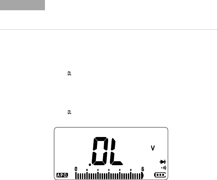
• A diode is considered open if the multimeter displays
in both forward and reverse bias modes.
Figure 2-13 Open diode display
NOTE
If the beeper is enabled during diode test, the multimeter will beep briefly
for a normal junction and sound continuously for a shorted junction, below
0.050 V. See “Changing the beep frequency” on page 87 to disable the
beeper.