
User`s guide


Table Of Contents
- Agilent U1231A, U1232A, and U1233A Handheld Digital Multimeter
- Table of Contents
- List of Figures
- List of Tables
- Introduction
- Making Measurements
- Multimeter Features
- Multimeter Setup Options
- Using the Setup Menu
- Setup Menu Summary
- Setup Menu Items
- Changing the variation count
- Enabling and changing the Smooth refresh rate
- Enabling and changing the voltage alert level
- Changing the beep frequency
- Changing the auto power-off (APO) timeout
- Changing the LCD backlight timeout
- Adjusting the LCD backlight intensity
- Enabling the LED flashlight timeout
- Adjusting the LED flashlight intensity
- Changing the minimum measurable frequency
- Changing the continuity test alerts
- Changing the power-on greeting tone
- Resetting the Setup items
- Changing the scale conversion value
- Enable the AC/DC mV measurement
- Enable open continuity test by default
- Changing the temperature unit
- Characteristics and Specifications
Making Measurements 2
Testing Diodes
U1231A/U1232A/U1233A User’s Guide 45
Tes ting Diode s
Set up your multimeter to test diodes as shown in
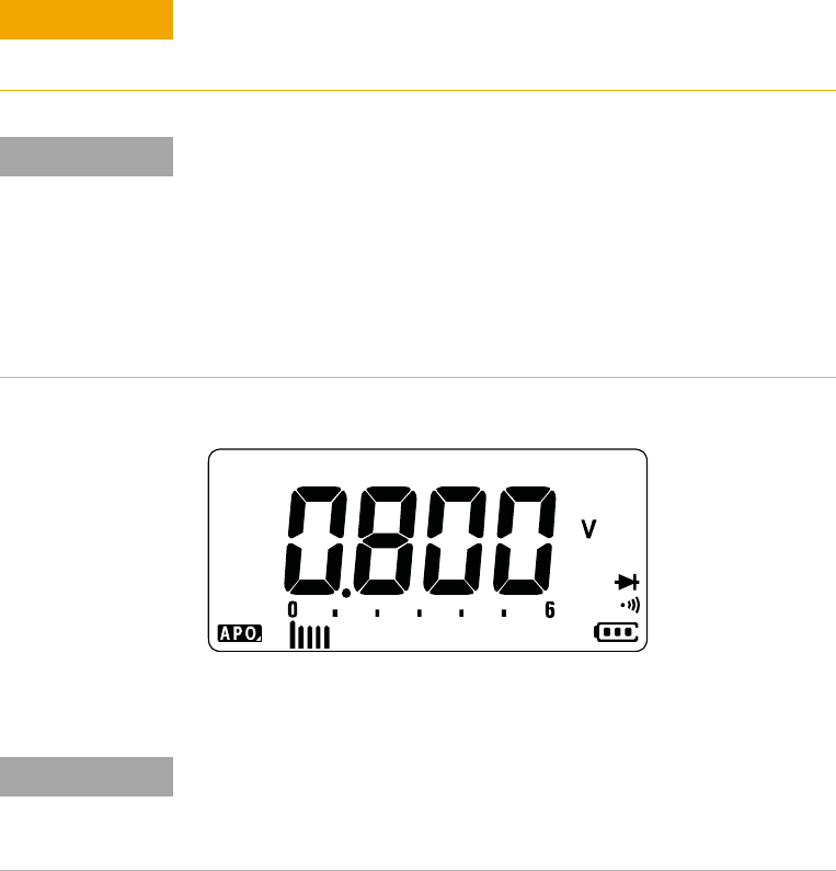
Figure 2- 14. Probe the test points and read the display.
Figure 2-12 Diode display
CAUTION
To avoid possible damage to your multimeter or to the equipment under
test, disconnect the circuit power and discharge all high-voltage
capacitors before testing diodes.
NOTE
• Use the diode test to check diodes, transistors, silicon controlled
rectifiers (SCRs), and other semiconductor devices. A good diode
allows current to flow in one direction only.
• This test sends a current through a semiconductor junction, and then
measures the junction’s voltage drop.
• Connect the red test lead to the positive terminal (anode) of the diode
and the black test lead to the negative terminal (cathode). The cathode
of a diode is indicated with a band.
NOTE
Your multimeter can display the forward bias of a diode up to
approximately 2.1 V. The forward bias of a typical diode is within the range
of 0.3 V to 0.8 V; however, the reading can vary depending on the
resistance of other pathways between the probe tips.