
User`s guide


Table Of Contents
- Agilent U1231A, U1232A, and U1233A Handheld Digital Multimeter
- Table of Contents
- List of Figures
- List of Tables
- Introduction
- Making Measurements
- Multimeter Features
- Multimeter Setup Options
- Using the Setup Menu
- Setup Menu Summary
- Setup Menu Items
- Changing the variation count
- Enabling and changing the Smooth refresh rate
- Enabling and changing the voltage alert level
- Changing the beep frequency
- Changing the auto power-off (APO) timeout
- Changing the LCD backlight timeout
- Adjusting the LCD backlight intensity
- Enabling the LED flashlight timeout
- Adjusting the LED flashlight intensity
- Changing the minimum measurable frequency
- Changing the continuity test alerts
- Changing the power-on greeting tone
- Resetting the Setup items
- Changing the scale conversion value
- Enable the AC/DC mV measurement
- Enable open continuity test by default
- Changing the temperature unit
- Characteristics and Specifications
2 Making Measurements
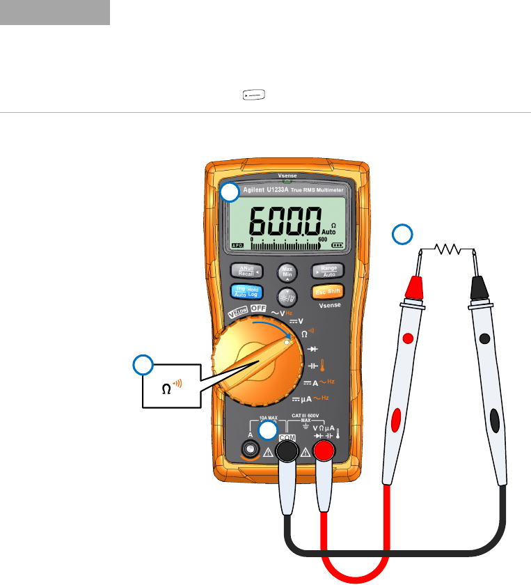
Measuring Resistance
40 U1231A/U1232A/U1233A User’s Guide
Figure 2-9 Measuring resistance
NOTE
• Because the multimeter’s test current flows through all possible paths
between the probe tips, the measured value of a resistor in a circuit is
often different from the resistor’s rated value.
• The resistance function can produce enough voltage to forward-bias
silicon diodes or transistor junctions, causing them to conduct. If this is
suspected, press to apply a lower current in the next higher range.
A
u
t
o
R
a
n
g
e
4
1
3
Resistor
2