
User`s guide


Table Of Contents
- Agilent U1231A, U1232A, and U1233A Handheld Digital Multimeter
- Table of Contents
- List of Figures
- List of Tables
- Introduction
- Making Measurements
- Multimeter Features
- Multimeter Setup Options
- Using the Setup Menu
- Setup Menu Summary
- Setup Menu Items
- Changing the variation count
- Enabling and changing the Smooth refresh rate
- Enabling and changing the voltage alert level
- Changing the beep frequency
- Changing the auto power-off (APO) timeout
- Changing the LCD backlight timeout
- Adjusting the LCD backlight intensity
- Enabling the LED flashlight timeout
- Adjusting the LED flashlight intensity
- Changing the minimum measurable frequency
- Changing the continuity test alerts
- Changing the power-on greeting tone
- Resetting the Setup items
- Changing the scale conversion value
- Enable the AC/DC mV measurement
- Enable open continuity test by default
- Changing the temperature unit
- Characteristics and Specifications
Making Measurements 2
Measuring Resistance
U1231A/U1232A/U1233A User’s Guide 39
Measuring Resistance
Set up your multimeter to measure resistance as shown in
Figure 2- 9. Probe the test points and read the display.
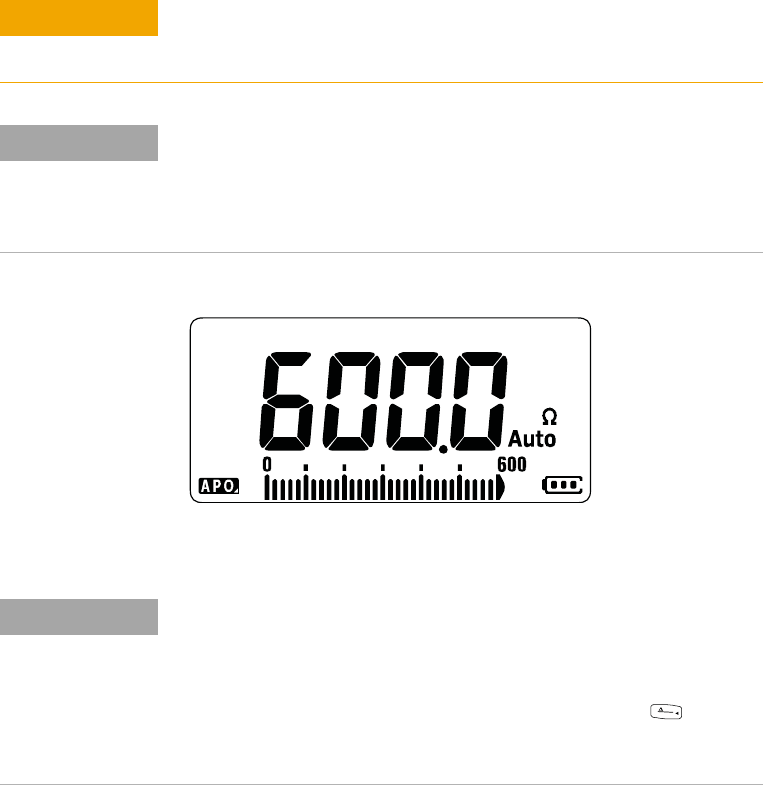
Figure 2-8 Resistance display
CAUTION
To avoid possible damage to your multimeter or to the equipment under
test, disconnect the circuit power and discharge all high-voltage
capacitors before measuring resistance.
NOTE
Resistance (opposition to the current flow) is measured by sending a small
current out through the test leads to the circuit under test. Because this
current flows through all possible paths between the leads, the resistance
reading represents the total resistance of all paths between the leads.
Resistance is measured in ohms (Ω).
NOTE
Keep the following in mind when measuring resistance.
• The test leads can add 0.1 Ω to 0.2 Ω of error to resistance
measurements. To test the leads, touch the probe tips together and
read the resistance of the leads. To remove lead resistance from the
measurement, hold the test lead tips together and press . Now the
resistance at the probe tips will be subtracted from all future display
readings.
N
u
l
l
R
e
c
a
l
l