
User`s guide


Table Of Contents
- Agilent U1231A, U1232A, and U1233A Handheld Digital Multimeter
- Table of Contents
- List of Figures
- List of Tables
- Introduction
- Making Measurements
- Multimeter Features
- Multimeter Setup Options
- Using the Setup Menu
- Setup Menu Summary
- Setup Menu Items
- Changing the variation count
- Enabling and changing the Smooth refresh rate
- Enabling and changing the voltage alert level
- Changing the beep frequency
- Changing the auto power-off (APO) timeout
- Changing the LCD backlight timeout
- Adjusting the LCD backlight intensity
- Enabling the LED flashlight timeout
- Adjusting the LED flashlight intensity
- Changing the minimum measurable frequency
- Changing the continuity test alerts
- Changing the power-on greeting tone
- Resetting the Setup items
- Changing the scale conversion value
- Enable the AC/DC mV measurement
- Enable open continuity test by default
- Changing the temperature unit
- Characteristics and Specifications
Making Measurements 2
Using VZ
LOW
for Voltage Measurements
U1231A/U1232A/U1233A User’s Guide 37
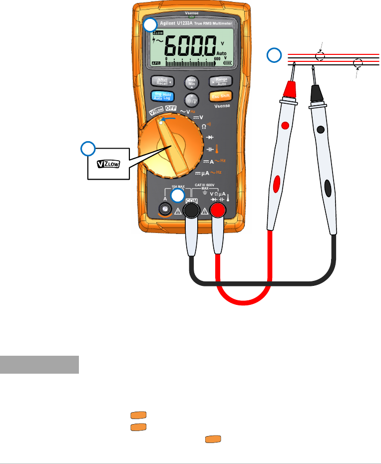
Figure 2-6 Measuring VZ
LOW
voltage
4
1
3
Adjacent unused wiring
2
Energized wiring
NOTE
• The multimeter will automatically identify the voltage measurement
based on the following criteria:
• If AC V > 0.5 V or AC V ≥ the absolute of DC V, AC V will be selected.
• Otherwise, DC V will be selected.
• Press once to lock the initial signal identification (AC V or DC V).
Press again to exchange the AC and DC voltage indication on the
primary display. Pressing for the third time will restart the auto
identification of the signal. See Figure 2-7 to learn more.
S
h
i
f
t
E
s
c
S
h
i
f
t
E
s
c
S
h
i
f
t
E
s
c