
User`s guide


Table Of Contents
- Agilent U1231A, U1232A, and U1233A Handheld Digital Multimeter
- Table of Contents
- List of Figures
- List of Tables
- Introduction
- Making Measurements
- Multimeter Features
- Multimeter Setup Options
- Using the Setup Menu
- Setup Menu Summary
- Setup Menu Items
- Changing the variation count
- Enabling and changing the Smooth refresh rate
- Enabling and changing the voltage alert level
- Changing the beep frequency
- Changing the auto power-off (APO) timeout
- Changing the LCD backlight timeout
- Adjusting the LCD backlight intensity
- Enabling the LED flashlight timeout
- Adjusting the LED flashlight intensity
- Changing the minimum measurable frequency
- Changing the continuity test alerts
- Changing the power-on greeting tone
- Resetting the Setup items
- Changing the scale conversion value
- Enable the AC/DC mV measurement
- Enable open continuity test by default
- Changing the temperature unit
- Characteristics and Specifications
1 Introduction
Your Multimeter in Brief
28 U1231A/U1232A/U1233A User’s Guide
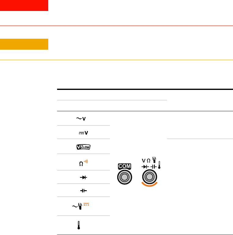
Input terminals
The terminal connections for the different measurement
functions of your multimeter are described in the table
below. Observe the rotary switch position of your multimeter
before connecting the test leads to the connector terminals.
WARNING
Ensure that the probe accessories are connected to the correct input
terminals for the selected measurement function before starting any
measurement.
CAUTION
To avoid damaging this device, do not exceed the rated input limit.
Table 1 - 10 U1231A terminal connections for different measuring functions
Rotary switch position Input terminals
Overload protection
U1231A
600 Vrms
600 Vrms for
short circuit <0.3 A
Hz
AUX
Hz
AUX