Agilent GUI Data Logger Software for U1230 Series, U1240 Series, U1250 Series, and U1270 Series Quick Start Guide Agilent Technologies
Notices © Agilent Technologies, Inc. 2006-2011 Warranty No part of this manual may be reproduced in any form or by any means (including electronic storage and retrieval or translation into a foreign language) without prior agreement and written consent from Agilent Technologies, Inc. as governed by United States and international copyright laws. The material contained in this document is provided “as is,” and is subject to change, without notice, in future editions.
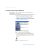
Table of Contents Introduction 1 System requirements 1 Installing and Connecting the Multimeter Data Logging/Virtual Meter 2 7 Downloading Data from the Multimeter 13 Square Wave Mode (for U1252A, U1253A, U1252B, and U1253B) 14 Remote Controls Agilent GUI Data Logger Quick Start Guide 16 III
IV Agilent GUI Data Logger Quick Start Guide
Introduction Introduction The U1231A, U1232A, U1233A, U1241A, U1242A, U1241B, U1242B, U1251A, U1252A, U1253A, U1251B, U1252B, U1253B, U1271A, U1272A, and U1273A multimeter models are equipped with a bi- directional (full duplex) communication capability that eases data storing from the multimeter to your PC.
Installing and Connecting the Multimeter Installing and Connecting the Multimeter NOTE You are recommended to disconnect the U1173A IR-USB cable before installing the software. 1 Download the Agilent GUI Data Logger Software for U1230 Series, U1240 Series, U1250 Series, and U1270 Series from http://www.agilent.com/find/hhTechLib. 2 Click to begin the installation. The required drivers and Microsoft .NET Framework are automatically installed if they are not detected on your PC.
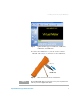
Installing and Connecting the Multimeter Figure 3 Agilent GUI Data Logger for U1230 Series, U1240 Series, U1250 Series, and U1270 Series 4 Connect the multimeter to your PC via the U1173A IR- USB cable (Figure 4) and turn on the multimeter. To PC (host) IR-USB cable Figure 4 NOTE Cable connection for remote communication The U1173A IR-USB cable is an optional accessory. You can purchase the cable at your nearest Agilent Sales Office.
Installing and Connecting the Multimeter 5 Click on the Communication panel to configure the multimeter’s communication settings. i Select Auto (Figure 5) to allow the Agilent GUI Data Logger to automatically search for a connected multimeter. ii Select Manual (Figure 5) to manually update the Agilent GUI Data Logger’s communication settings. Select the communication Port that your multimeter is connected to. Clicking Update port will update the port selections that are available on your PC.
Installing and Connecting the Multimeter 6 Click Connect. If the Agilent GUI Data Logger’s communication settings matches with the multimeter’s communication settings, the Meter Connected notification will be shown in the status bar (Figure 6). Figure 6 Meter connection success 7 If the connection fails (Figure 7), check that the U1173A IR- USB cable is connected securely to the multimeter and that the multimeter is turned on.
Installing and Connecting the Multimeter Figure 8 6 Properties panel Agilent GUI Data Logger Quick Start Guide
Data Logging/Virtual Meter Data Logging/Virtual Meter 1 Set the rotary switch of the multimeter to the position of the preferred measuring function. NOTE To know more about the functions at different rotary switch positions, refer to the ve multimeter’s User’s Guide. 2 Click the .icon and click the icon. 3 The measured value from the multimeter is shown on the Virtual Meter. Click the Virtual Meter tab to see the Virtual Meter. (Figure 9).
Data Logging/Virtual Meter 4 Measurement data from the multimeter is captured automatically and sorted in the Data Logging Table. Click the Data Logging Table tab to see the Data Logging Table. (Figure 10). Figure 10 NOTE 8 Data Logging Table The Data Logging Table and Virtual Meter are running simultaneously. Figure 11 shows the data logging process.
Data Logging/Virtual Meter Click Data Logging to enable the data logging feature. Click Run to start acquiring data. Click Pause to pause the acquisition process. Click Stop to stop acquiring data. NO Clear the acquired data. Click Yes to save the acquired data. YES Save the acquired data.
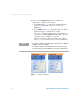
Data Logging/Virtual Meter 5 You can set the saved data location in the Data Logging Table tab. i Double click Directory: ... as shown in Figure 12. Figure 12 Directory ii The Select your directory and filename dialog box will appear (Figure 13). Select a file name and path, and click Save. Figure 13 Select your directory and filename 6 You can choose to log the measurement data shown in the secondary display. NOTE This option is not available for the U1231A, U1232A, and U1233A models.
Data Logging/Virtual Meter Figure 14 NOTE Secondary You can change the maximum number of records in the Data Logging Table by clicking Preferences > Options. 7 Click the Shows menu (Figure 15) to customize the column display preference. Figure 15 Column display customization 8 To display the measured data in the form of a strip graph, click on the Graphs tab. These graphs are meant for display purposes only.
Data Logging/Virtual Meter Figure 16 12 Graph function Agilent GUI Data Logger Quick Start Guide
Downloading Data from the Multimeter Downloading Data from the Multimeter NOTE • This option is not available for the U1231A, U1232A, and U1233A models. • The event log entries download is only available for U1271A, U1272A, and U1273A models. 1 You can transfer the data from your multimeter to your PC through the Agilent GUI Data Logger.
Downloading Data from the Multimeter Figure 18 14 Memory context menu Agilent GUI Data Logger Quick Start Guide
Square Wave Mode (for U1252A, U1253A, U1252B, and U1253B) Square Wave Mode (for U1252A, U1253A, U1252B, and U1253B) NOTE This option is not available for the U1231A, U1232A, U1233A, U1251A, U1251B, U1271A, U1272A, and U1273A models. 1 Turn the rotary switch of the multimeter to the position. 2 Click the icon to activate the square wave mode.
Square Wave Mode (for U1252A, U1253A, U1252B, and U1253B) 2 Drag and drop the frequency value into the Frequency column cell in the table (Figure 20). 3 Select the ve Duty Cycle and Duration column cell and then click Fill in the selected cell button to input the parameters (Figure 20). Drag the frequency value down Select the cell and click Fill in the selected cell.
Remote Controls Remote Controls The Secondary display remote controls are not available for the U1231A, U1232A, and U1233A models. NOTE 1 The multimeter can be controlled remotely according to the rotary switch position selected. 2 Click Update Command, to update the list of commands available for the rotary switch position selected. The list of commands can be viewed through the drop- down combo box menu (Figure 21). 3 Click Send Command to send the selected command parameters to the multimeter.
Remote Controls 18 Agilent GUI Data Logger Quick Start Guide
www.agilent.