
User`s guide

88 Agilent 34980A Mainframe User’s Guide
3 Features and Functions
Custom A/D Integration Time
Integration time is the period of time the internal DMM’s analog- to- digital
(A/D) converter samples the input signal for a measurement. Integration
time affects the measurement resolution (for better resolution, use a longer
integration time) and measurement speed (for faster measurements, use a
shorter integration time). The default integration time is 1 PLC.
• Integration time is specified in number of power line cycles (PLCs).
Select from 0.02, 0.2, 1, 2, 10, 20, 100, or 200 power line cycles.
• Only integral number of power line cycles (1, 2, 10, 20, 100, or 200
PLCs) provide normal mode (line frequency noise) rejection.
• You can also specify integration time in seconds (this is called aperture
time). Select a value from 300 µs and 1 second, with 4 µs resolution.
• The only way to control the reading rate for ac measurements is by
changing the channel delay (see “Channel Delay” on page 120) or by
setting the ac filter to the highest frequency limit (see “AC Low
Frequency Filter” on page 102).
• The specified integration time is used for all measurements on the
selected channel. If you have applied Mx+B scaling, have assigned
alarms to the selected channel or are using Monitor mode, those
measurements are also made using the specified integration time.
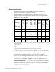
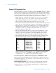
• The following table shows the relationship between integration time,
measurement resolution, number of digits, and number of bits.
• The instrument selects 1 PLC when the measurement function is
changed and after a Factory Reset (
*RST command). An Instrument
Preset (
SYSTem:PRESet command) or Card Reset (SYSTem:CPON
command) does not change the integration time setting.
Front Panel Operation: DMM or Channel (Configure) > INTEGRATION > TIME
First, select the measurement function on the active channel. You are
automatically guided to the next level of the menu where you can select
a specific integration time.
Remote Interface Operation: You can set the integration time using the
SENSe commands. For example, the following command specifies an
aperture time of 2 ms for resistance measurements on channel 2001.
SENS:RES:APER 0.002,(@2001)
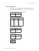
Integration Time Resolution Digits Bits
0.02 PLC
0.2 PLC
1 PLC
2 PLC
10 PLC
20 PLC
100 PLC
200 PLC
< 0.0001 x Range
< 0.00001 x Range
< 0.000003 x Range
< 0.0000022 x Range
< 0.000001 x Range
< 0.0000008 x Range
< 0.0000003 x Range
< 0.00000022 x Range
4½ Digits
5½ Digits
5½ Digits
6½ Digits
6½ Digits
6½ Digits
6½ Digits
6½ Digits
15
18
20
21
24
25
26
26