
User`s guide

26 Agilent 34980A Mainframe User’s Guide
2 Getting Started
Installing and Connecting Modules
For most applications, prior to using the 34980A you will select and
install modules, and make connections with terminal blocks or cabling.
The following sections illustrate module and terminal block installation.
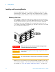
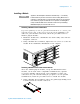
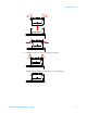
Removing a Slot Cover
Your 34980A is shipped from the factory with one slot uncovered and
the remaining seven slots covered (the illustration below shows a module
already inserted in Slot 1). When you are ready to install additional
modules in the seven remaining slots, you must first remove its slot
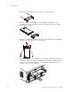
cover. Using a flat blade screwdriver, pry each side of the slot cover until
the cover releases from the slot.
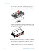
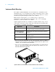
With the slot cover removed, you can now install a module in this slot.
For detailed examples of the slot and channel numbering scheme used in
the 34980A, see “Slot and Channel Addressing Scheme” on page 166.
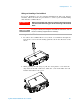
WARNING
When any slot covers are removed, hazardous voltages may be
exposed on the analog bus connectors.
CAUTION
Install current limiting devices between high energy sources and the
module inputs.
CAUTION
Do not block air intake or exhaust vents at the sides of the instrument