
User`s guide

8 Agilent 34980A Mainframe User’s Guide
1 Introduction to the 34980A
Signal Routing and Switching
The switching capabilities of the plug- in modules available with the
34980A provide test system flexibility and expandability. You can use the
switching plug- in modules to route signals to and from your test system
or multiplex signals to the internal DMM or external instruments.
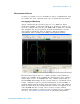
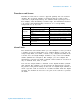
Relays are electromechanical devices which are subject to wear- out
failure modes. The life of a relay, or the number of actual operations
before failure, is dependent upon how the relay is used—applied load,
switching frequency, and environment. The 34980A Relay Maintenance
System automatically counts the cycles of each relay in the instrument
and stores the total count in non- volatile memory on each switch
module. You can use this feature to track relay failures and to predict
system maintenance requirements. For more information on using this
feature, refer to “Relay Cycle Count” on page 154.
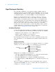
Switching Topologies
Several switching plug- in modules are available with different topologies
for various applications. The following switching topologies are available:
• Multiplexer (with armature, reed, or FET switches)
• Matrices (with armature or reed switches )
• General Purpose (with Form C or Form A switches)
The following sections describe each of these switching topologies. For
more information, see the individual User's Guides included with each
module.
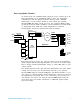
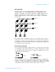
Multiplexer Switching
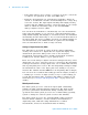
Multiplexers allow you to connect one of multiple channels to a common
channel, one at a time. A simple 4- to- 1 multiplexer is shown below.
Multiplexers are available in several types:
• One- Wire (Single- Ended) Multiplexers for common LO measurements
• Two- Wire Multiplexers for floating measurements
• Four- Wire Multiplexers for resistance and RTD measurements
• Very High Frequency (VHF) Multiplexers for switching frequencies up
to 3 GHz.
When you combine a multiplexer with a measurement device, like the
optional internal DMM, you create a scanner. For more information on
scanning, see “Scanning” on page 13.
Common
Channel 2
Channel 3
Channel 4
Channel 1