
User`s guide

Introduction to the 34980A 1
Agilent 34980A Mainframe User’s Guide 5
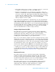
Data Acquisition Circuitry
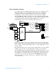
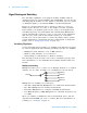
As shown below, the 34980A's main system processor controls all of the
basic functionality of the instrument. This is where the instrument
communicates with the plug- in modules, interacts with command
transactions over the remote interfaces, and controls the optional
internal DMM. The main system processor also performs Mx+B scaling
operations, monitors alarm conditions, converts transducer measurements
to engineering units, adds time stamp information to scanned
measurements, and stores measurement data in memory.
The main system processor also controls activity on the four hardware
alarm outputs and external triggering lines. You can use the alarm output
lines to trigger external alarm lights, sirens, or send a TTL pulse to your
control system.
The 34980A provides four 2- wire internal Analog Buses for easier signal
routing. You can route your measurements directly to the optional
internal DMM using the 34980A multiplexer and matrix modules or you
can connect to external signals via the Analog Bus connector located on
the instrument's rear panel. Since four 2- wire buses are provided, you
can dedicate one bus for use with the internal DMM while using the
other three buses for module extensions or additional signal routing
between modules.
Main
System
Processor
GPIB
USB
LAN
Slot
1000
Slot
3000
Slot
8000
Slot
2000
Optional
Internal
DMM
Control
Analog
Bus
Alarms
OUT
IN
External
Trigger
ABUS1
ABUS4
ABUS3
ABUS2
AC
Power
I
Hi Measure
Lo Measure
Hi Sense
Lo Sense
Digital Bus