Agilent 34980A Multifunction Switch/Measure Unit Mainframe User’s Guide Agilent Technologies, Inc.
Notices © Agilent Technologies, Inc. 2004-2012 Declaration of Conformity Restricted Rights Legend No part of this manual may be reproduced in any form or by any means (including electronic storage and retrieval or translation into a foreign language) without prior agreement and written consent from Agilent Technologies, Inc. as governed by United States and international copyright laws. Declarations of Conformity for this product and for other Agilent products may be downloaded from the Web.
Additional Safety Notices The following general safety precautions must be observed during all phases of operation of this instrument. Failure to comply with these precautions or with specific warnings or instructions elsewhere in this manual violates safety standards of design, manufacture, and intended use of the instrument. Agilent Technologies assumes no liability of the customer’s failure to comply with the requirements.
Contents 1 Introduction to the 34980A Data Acquisition Overview. . . . . . . . . . . . . . . . . . . . . . . . . . . . . . . . . . . . . . . . . . . . . 2 Measurement Software . . . . . . . . . . . . . . . . . . . . . . . . . . . . . . . . . . . . . . . . . . . . . 3 Data Acquisition Circuitry . . . . . . . . . . . . . . . . . . . . . . . . . . . . . . . . . . . . . . . . . . . 5 Plug-In Modules. . . . . . . . . . . . . . . . . . . . . . . . . . . . . . . . . . . . . . . . . . . . . . . . . . .
Menu Example 4: Configuring a Channel for a Measurement . . . . . . . . . . . . . . 42 Connecting the 34980A to Your Computer. . . . . . . . . . . . . . . . . . . . . . . . . . . . . . . . 45 Connecting Over LAN . . . . . . . . . . . . . . . . . . . . . . . . . . . . . . . . . . . . . . . . . . . . . 46 Connecting Over GPIB . . . . . . . . . . . . . . . . . . . . . . . . . . . . . . . . . . . . . . . . . . . . 51 Connecting Over USB . . . . . . . . . . . . . . . . . . . . . . . . . . . . . . . . . . . . . .
2-Wire Versus 1-Wire Mode . . . . . . . . . . . . . . . . . . . . . . . . . . . . . . . . . . . . . . . . 95 Temperature Measurement Configuration . . . . . . . . . . . . . . . . . . . . . . . . . . . . . . . . 96 Measurement Units . . . . . . . . . . . . . . . . . . . . . . . . . . . . . . . . . . . . . . . . . . . . . . . 96 Thermocouple Measurements . . . . . . . . . . . . . . . . . . . . . . . . . . . . . . . . . . . . . . . 97 RTD Measurements. . . . . . . . . . . . . . . . . . . . . . . . . . . . . .
Error Conditions. . . . . . . . . . . . . . . . . . . . . . . . . . . . . . . . . . . . . . . . . . . . . . . . . 150 Self-Test . . . . . . . . . . . . . . . . . . . . . . . . . . . . . . . . . . . . . . . . . . . . . . . . . . . . . . . 151 Front-Panel Display Control . . . . . . . . . . . . . . . . . . . . . . . . . . . . . . . . . . . . . . . 151 Front-Panel Number Format . . . . . . . . . . . . . . . . . . . . . . . . . . . . . . . . . . . . . . . 152 Real-Time System Clock . . . . . . . . . . . . . . .
Agilent 34980A Multifunction Switch/Measure Unit Mainframe User’s Guide 1 Introduction to the 34980A This chapter provides an overview of a computer- based data acquisition and measurement control system using the Agilent 34980A Multifunction Switch/Measure Unit and typical plug- in modules.
1 Introduction to the 34980A Data Acquisition Overview You can use the Agilent 34980A as a stand- alone instrument, but for most applications you will want to take advantage of its PC connectivity and remote operation capabilities. A simplified data acquisition system is shown below.
1 Introduction to the 34980A Measurement Software A variety of software tools are available for remote communication with the 34980A; the most commonly used tools are briefly discussed below. Data Logging and Monitoring Agilent 34832A BenchLink Data Logger Pro is a Windows®- based application available on CD from Agilent. It is designed to make it easy to use the 34980A with your PC (over GPIB, USB or LAN) for collecting and analyzing data.
1 Introduction to the 34980A Web Browser Interface The 34980A incorporates in its firmware a graphic Web Browser interface for remote LAN access and control of the instrument via a Java- enabled Web browser, such as Microsoft® Internet Explorer. While not as comprehensive a tool as the BenchLink Data Logger software, the Web Browser provides an alternative method for remote system configuration, troubleshooting, and monitoring.
1 Introduction to the 34980A Data Acquisition Circuitry As shown below, the 34980A's main system processor controls all of the basic functionality of the instrument. This is where the instrument communicates with the plug- in modules, interacts with command transactions over the remote interfaces, and controls the optional internal DMM.
1 Introduction to the 34980A Plug-In Modules The 34980A offers a complete selection of plug- in modules to give you high- quality measurement, switching, and control capabilities. The plug- in modules communicate with the main system processor via the internal digital bus. The multiplexer modules also connect to the internal DMM via the internal Analog Buses. Each module has its own microprocessor to offload the main system processor and minimize backplane communications for faster throughput.
1 Introduction to the 34980A Transducers and Sensors Transducers and sensors convert a physical quantity into an electrical quantity. The electrical quantity is measured and the result is then converted to engineering units by the 34980A's main system processor. For example, when measuring a thermocouple, the instrument measures a dc voltage and mathematically converts it to a corresponding temperature in °C, °F, or K.
1 Introduction to the 34980A Signal Routing and Switching The switching capabilities of the plug- in modules available with the 34980A provide test system flexibility and expandability. You can use the switching plug- in modules to route signals to and from your test system or multiplex signals to the internal DMM or external instruments. Relays are electromechanical devices which are subject to wear- out failure modes.
1 Introduction to the 34980A Matrix Switching A matrix switch connects multiple inputs to multiple outputs and therefore offers more switching flexibility than a multiplexer. Use a matrix for switching low- frequency (less than 30 MHz) signals only. A matrix is arranged in rows and columns. For example, a simple 3x3 matrix could be used to connect three sources to three test points as shown below.
1 Introduction to the 34980A RF and Microwave Switching A variety of RF and microwave switch modules are also available for the 34980A. This includes RF multiplexers (34941A, 34942A), SPDT switching from dc to 20 GHz (34946A, 34947A), and a switch/attenuator driver module (34945A) that allows you to control switches or attenuators external to the 34980A mainframe. For more information, see “Introduction to the Plug- In Modules for the 34980A” on page 163.
1 Introduction to the 34980A Measurement Input The 34980A allows you to combine a DMM (either internal or external) with multiplexer channels to create a scan. During a scan, the instrument connects the internal DMM to the configured multiplexer channels one at a time and makes a measurement on each channel. Any channel that can be "read" by the instrument can also be included in a scan.
1 Introduction to the 34980A • If the input signal is an ac voltage, a converter is used to convert the ac signal to its equivalent dc value (true RMS value). • Resistance measurements are performed by supplying a known dc current to an unknown resistance and measuring the dc voltage drop across the resistor.
1 Introduction to the 34980A Scanning The instrument allows you to combine a DMM (either internal or external) with multiplexer channels to create a scan. During a scan, the instrument connects the DMM to the configured multiplexer channels one at a time and makes a measurement on each channel. Before you can initiate a scan, you must set up a scan list to include all desired multiplexer or digital channels. Channels which are not in the scan list are skipped during the scan.
1 Introduction to the 34980A • You can manually control a scan by repeatedly pressing the Scan (Measure) key from the front panel. • You can start a scan by sending a software command from the remote interface (MEASure? or INITiate command). • You can start a scan when an external TTL trigger pulse is received. • You can start a scan when an alarm event is logged on the channel being monitored. For more information on scanning, see “Scanning” on page 108.
1 Introduction to the 34980A The figure below shows the external connections required to synchronize the scan sequence between the 34980A and an external instrument. The 34980A must notify the external instrument when a relay is closed and fully settled (including channel delay). The 34980A outputs a Channel Closed pulse. In response, the external instrument must notify the 34980A when it has finished its measurement and is ready to advance to the next channel in the scan list.
1 Introduction to the 34980A The Digital Modules The 34950A and 34952A digital modules add two additional measurement input capabilities to the system: digital input and event totalize. For more information, see the individual User's Guides included with those modules. Digital Input The digital modules have multiple non- isolated 8- bit input/output ports which you can use for reading digital patterns.
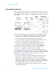
1 Introduction to the 34980A Totalizer The digital modules have 32- bit totalizer input channels for counting pulses and measuring frequency. You can manually read the totalizer count or you can configure a scan to read the count. Count + Count - 32 Bits Totalizer Gate Gate You can configure the totalizer to count on the rising edge or falling edge of the input signal. The minimum rise/fall time for input signals to the totalizer is 5 S. The maximum count is 4,294,967,295 (232 - 1).
1 Introduction to the 34980A Control Output In addition to signal routing and measurement, you can also use the 34980A to provide simple control outputs. For example, you can control external high- power relays using the GP switch modules or a digital output channel. The Digital Modules The 34950A, 34951A and 34952A digital modules add two additional measurement control output capabilities to the system: digital output and voltage (DAC) output.
1 Introduction to the 34980A Voltage (DAC) Output The 34951A module has four independent, isolated analog output channels that can output dc voltage up to 16V or dc current up to 20 mA. Each DAC (Digital- to- Analog Converter) channel can be used as a programmable voltage source for analog input control of other devices. A simplified diagram is shown below.
1 Introduction to the 34980A The Actuator / General-Purpose Switches You can think of the 34937A, 34938A, and 34939A modules as a control outputs because they are often used to control external power devices. For example, the 34937A provides 28 independent, isolated Form C (SPDT) switches. Each channel can switch up to 300V dc or ac rms. Each switch can also switch up to 1A dc or ac rms up to 60W maximum. For example, the maximum current that you can switch at 120V is 0.45A as shown below.
Agilent 34980A Multifunction Switch/Measure Unit Mainframe User’s Guide 2 Getting Started This chapter provides an overview of the 34980A’s controls, displays and connections; module assembly, wiring and installation instructions; and some basics of operation with examples. It is designed to allow you to gain quick familiarity with the instrument and start using it.
2 Getting Started Front Panel at a Glance 1 2 3 4 5 6 7 8 9 10 11 12 13 22 The On/Standby switch is used to toggle the 34980A between On and Standby modes only. To turn the unit off, remove the power cord. The Utility key accesses menus to configure Remote I/O (LAN, GPIB, and USB) operation, set Date and Time, and configure other system-related instrument parameters. The Store/Recall key allows you to save and recall up to six instrument setups. Control keys directly control module actions.
2 Getting Started Rear Panel at a Glance Safety Symbols Located on Rear Panel Warning. Risk of electric shock Caution. Refer to accompanying descriptions in User’s Guide Alternating Current Mainframe Chassis Ground 1 2 3 4 5 6 7 8 9 10 11 12 Access to Analog Buses (shown with removable cover installed). For pinouts, see page 24. Module installed in slot 1 Slot identifier Module ground screw Slot cover over slot 2 AC power connector LAN connector (10Base T/100Base Tx) USB 2.
2 Getting Started Rear Panel Connector Pinouts External Trigger/Alarms Connector (Male D-Sub) Analog Bus Connector (Female D-Sub) 24 Agilent 34980A Mainframe User’s Guide
2 Getting Started Annunciator Display Indicators Display Indicator LAN USB GPIB ABUS [1234] ERROR Rmt Safety Interlock Trig HOT ALARM (H1234L) Mx+B 4W OC * Definition Lit when communicating with the 34980A over LAN. Lit when communicating with the 34980A over USB. Lit when communicating with the 34980A over GPIB. Indicates Analog Bus (ABus) connectivity. Normally, this shows the designated ABus connected on any module in the mainframe.
2 Getting Started Installing and Connecting Modules For most applications, prior to using the 34980A you will select and install modules, and make connections with terminal blocks or cabling. The following sections illustrate module and terminal block installation. Removing a Slot Cover Your 34980A is shipped from the factory with one slot uncovered and the remaining seven slots covered (the illustration below shows a module already inserted in Slot 1).
2 Getting Started Installing a Module NOT E Applies to the multiplexer and matrix modules only — The Safety Interlock feature prevents connections to the Analog Buses from a module if a terminal block or properly-wired cable is not connected to that module. If proper connections are not present, the Analog Bus relays will be disabled on that module and the front panel Safety Interlock display annunciator will turn on.
2 Getting Started 2 Remove the two flathead screws from the support sleeve. 3 Fit the terminal block support sleeve against the module so the openings on the sleeve line up with the connectors and the center screw hole as shown. 4 Replace the panhead screw. Then replace and tighten the two flathead screws to secure the sleeve to the module. 5 Install the module into a mainframe slot until it fully seats with the backplane connector.
2 Getting Started Wiring and Installing a Terminal Block If you are planning to use an optional terminal block with your plug- in modules, follow the next two procedures to connect your external wiring and install a terminal block. WA RNING Before you begin this task, make sure you have disconnected power from all external field wiring you will be connecting to the terminal block.
2 Getting Started 3 Make connections to the individual terminals as appropriate. Use a suitable wire type, gauge and insulation for your application (typical is 20 AWG; the terminals can accommodate a maximum of 18 AWG). Use a 2.5 mm cable tie as shown for additional strain relief. Wire Size: 20 AWG (typical); 18 AWG (max) 6 mm 4 To replace the terminal block cover, slide the cover tabs into the tab holders on the terminal block as shown. Press down on the cover until it snaps securely into place.
2 Getting Started Terminal Block Support Sleeve 34980A Mainframe 2 Carefully rotate the levers upward as shown… …until both levers are locked in the closed position.
2 Getting Started Instrument Rack Mounting The Agilent 34980A Mainframe can be mounted in a standard 19 inch instrument rack or in an Agilent rack cabinet. Orientation can be either forward mounted (front panel facing the front of the cabinet) or reverse mounted (rear panel facing the front of the cabinet). Either method will require a set of cabinet rails to support the instrument’s weight and planned orientation, and a set of mounting brackets to secure the unit to the cabinet.
2 Getting Started 425.6 mm (16.76 in) 367.7 mm (14.48 in) 101.9 mm (4.01 in) or 70.4 mm (2.
2 Getting Started Operating the 34980A from the Front Panel Keyboard This section gives an overview on operating the 34980A from the front panel keyboard. The Front Panel Menu Reference subsection briefly describes the menus accessed by the front panel keys, and the subsequent subsections provide examples of menu navigation. NOT E Before you can operate the front panel keyboard, connect the power cord to the 34980A and turn on the power.
2 Getting Started Front Panel Menu Reference This subsection provides an overview of the top two levels of menus you can access from the front panel. The menus are designed to sequentially guide you through all parameters required to configure a particular function or operation. The Store/Recall Menu Use to store and recall instrument states.
2 Getting Started Configure Key Group Use these menus to set measurement parameters.
2 Getting Started Menu Example 1: Setting the Time and Date In this example, you will learn the fundamentals of using the 34980A front- panel menus by setting the date and time. Begin by pressing the Utility menu key, then use the Utility key, knob and arrow keys to navigate the menu as shown below. Follow the menu prompts as they are displayed. Utility ... REMOTE I/O Additional Choices DATE / TIME Use the knob to scroll through the choices on the same level.
2 Getting Started Menu Example 2: Opening and Closing Channel Relays This example is applicable for use with any of the multiplexer modules (34921A, 34922A, 34923A, 34924A, or 34925A); it illustrates a 34921A module installed in slot 1. 1 Using the number keypad, press 1 to select the slot containing the multiplexer module. 2 1 3 2 Select channel 27 on the module by pressing 2 and then 7. 3 Press the lighted ENTER key to complete your channel selection.
2 Getting Started Using the Measure Keys In Menu Examples 2 and 3 (the following two subsections), you will use keys in the front- panel Measure group. The three keys in the Measure group control the initiation of measurements (conversely, the menu keys in the Configure group allow you to set parameters for measurements).
2 Getting Started Menu Example 3: Configuring the DMM for a Measurement This example uses the internal DMM for a measurement. It can be used with any of the multiplexer modules (34921A, 34922A, 34923A, 34924A, or 34925A). If you have disabled your internal DMM, don't have one installed in your 34980A, or are not using a multiplexer module, skip this example. 1 Make sure you have a multiplexer module installed in slot 1.
2 Getting Started 7 Within the Measure key group, press DMM. 7 Note that the key lights and continuous ac voltage measurements are made using the internal DMM. 8 To stop the measurements, press DMM (in the Measure key group). During This Tutorial Example: • You configured the internal DMM for ac voltage measurements, • You started measurements, viewed continuous measurement results, and stopped the measurements.
2 Getting Started Menu Example 4: Configuring a Channel for a Measurement This example uses the internal DMM for a measurement. It can be used with any of the multiplexer modules (34921A, 34922A, 34923A, 34924A, or 34925A). If you have disabled your internal DMM, don't have one installed in your 34980A, or are not using a multiplexer module, skip this example. 1 Make sure you have a multiplexer module installed in slot 1.
2 Getting Started 6 Use the knob to select the 100 mV range for the dc voltage function. 7 Continue pressing the lighted Channel key until CHANNEL LABEL is shown. 8 At the CHANNEL LABEL choice, use the knob (to select alphanumeric characters) and the arrow keys (to select the cursor position) to enter a custom channel label. 9 Press the lighted Channel key to save the assigned channel label and all other changes you made. 10 Press the Channel key (in the Measure key group).
2 Getting Started 11 To stop the continuous measurements, press Channel again. Note that as you press Channel, you will hear the relays automatically opening. 12 Using steps 1 through 6 on the previous page, set the following configuration for Channel 1014 (for this example, don't change any other measurement parameters): • Channel: 1014 • Measurement Function: AC Volts • Range: 1V 13 Press EXIT MENU to accept the new settings and retain all other parameters in this menu.
2 Getting Started Connecting the 34980A to Your Computer NOT E To easily configure and verify an interface connection between the 34980A and your PC, you can use the Agilent IO Libraries Suite or an equivalent. • The Agilent IO Libraries Suite—along with installation instructions—is provided on the Automation-Ready CD, which is shipped with your 34980A. • Previous versions of the Agilent IO Libraries software are also available.
2 Getting Started Connecting Over LAN Selecting the LAN network type You can connect and configure your 34980A for Site LAN or Isolated (non- site) LAN operation. • A Site LAN network is defined as a local area network (LAN) in which computers and LAN- enabled instruments are connected to a site LAN (workgroup LAN, Intranet, or enterprise LAN) via optional routers, hubs, and/or switches.
2 Getting Started Connecting Via Site LAN To Network Interface Card (NIC) To LAN Port To Site LAN Example Site LAN Connection PC 34980A 1 Using a standard LAN patch cable (not supplied), connect your computer and the 34980A to LAN wall outlets. 2 Make sure power is applied to your computer and verify that the operating system is fully booted. Then apply power to the 34980A. 3 Using the flow diagram shown below, navigate through the 34980A front- panel Utility menu. At the IO PORT menu, select LAN.
2 Getting Started 4 Press EXIT MENU, which saves any changes and defaults all other parameters in the Utility menu. 5 Wait for the DHCP server to assign a valid address; this operation can take between 30 seconds and one minute to complete). 6 From the Utility menu (see Navigation Flow Diagram on page 47), navigate to the LAN SETTINGS choice and select VIEW. Using the flow diagram as a guide, view the instrument's IP address and other LAN settings.
2 Getting Started Connecting Via Isolated (Non-Site) LAN To Network Interface Card (NIC) Example Isolated (Non-Site) LAN Connection To LAN Port CAT5 Crossover Cable PC 34980A 1 Using the CAT5 crossover cable provided with the 34980A, connect your computer to the 34980A. 2 Make sure power is applied to your computer and verify that the operating system is fully booted. Then apply power to the 34980A. 3 Using the flow diagram below, navigate through the 34980A front- panel Utility menu.
2 Getting Started 4 Press EXIT MENU, which saves any changes and defaults all other parameters in the Utility menu. 5 From the Utility menu, navigate to the LAN SETTINGS choice and select VIEW. Using the flow diagram ON page 49 as a guide, view the instrument's IP address and other LAN settings. Write down the IP address in the space below: 34980A IP Address: ___________________________ 6 Press EXIT MENU.
2 Getting Started Connecting Over GPIB 1 Make sure you have installed the required I/O software and device drivers on your computer. 2 Follow the instructions from your GPIB interface card’s vendor to install and configure the GPIB hardware in your computer. 3 Connect a GPIB cable (not provided) between your computer and the 34980A. 4 Make sure power is applied to your computer and verify that the operating system is fully booted. Then apply power to the 34980A.
2 Getting Started Connecting Over USB 1 Make sure you have installed the required I/O software and device drivers on your computer. 2 Connect a standard USB cable between your computer and the 34980A. 3 Make sure your computer and its operating system is fully booted. Then apply power to the 34980A. 4 The Found New Hardware Wizard will automatically start and guide you through configuring the 34980A as a USB device. To install the software automatically, accept all defaults.
2 Getting Started Communicating with the 34980A You can use either instrument drivers or SCPI (Standard Commands for Programmable Instruments) commands — in any programming environment — to communicate with the 34980A. However, Agilent has designed drivers that work best in recommended environments, as shown in the table below. To install drivers and their associated Help files, refer to the 34980A Product Reference CD shipped with your 34980A.
2 Getting Started Launching the Web Interface 1 Open your Internet browser from your computer. 2 From the Tools>Internet Options menu, navigate to Connections (exact navigation depends on your browser), and then select LAN Settings. 2 5 Click here for Help 3 From the LAN Settings dialog, select/activate the bypass proxy server for local addresses (exact terminology depends on your browser). 4 Exit the Internet Options window. 5 Enter the IP address of the 34980A in the Address field and press return.
2 Getting Started Displaying the Browser Web Control Page 1 From the Welcome Window, click the Browser Web Control tab on the left side of the window to display the Browser Web Control page. 1 2 2 From this page, you can view and modify the configuration of the modules currently installed in the 34980A. When you first launch this page, the configuration of the module in the lowest numbered slot is shown (shown in bold text).
2 Getting Started Selecting the “Allow Full Control” Mode Select the Allow Full Control radio button as shown. Once enabled, this mode allows you to open and close channel relays and modify the state of the installed modules. Setting a Web Browser Password If desired, you can control access to the 34980A Web Interface using password protection. As shipped from the factory, no password is set.
2 Getting Started Closing and Opening Channel Relays You must be in the Allow Full Control mode to close and open channels. NOT E 1 To close a channel, left- click directly on the graphic of the desired relay. To open a closed channel, click again on the relay graphic. 2 1 2 You can also open and close the four Analog Bus relays by left- clicking the graphics of these relays. The Analog Bus Overview display located near the top of the window shows the slot- by- slot status of the four Analog Buses.
2 Getting Started Modifying the Channel Configuration NOT E You must be in the Allow Full Control mode to modify the channel configuration. 1 To modify the measurement configuration of individual channels (e.g., add channel labels, select function and range, etc.), right- click directly on the graphic of the desired relay. The Channel Configuration dialog box for that channel is displayed. 1 2 2 As an example, change the label on Channel 1001 to DUT_1. Click OK.
2 Getting Started Sending SCPI Commands Via the Web Interface You must be in the Allow Full Control mode to send instrument commands to the 34980A. NOT E The Web Interface provides a utility to send SCPI commands to the 34980A via the SCPI Command Interface window. The procedure below shows how to access this window and send commands. 1 Press the Commands button at the top of the Web Browser Control page to launch the SCPI Command Interface window.
2 Getting Started b Select commonly used commands to send to the instrument. 2b c Enter SCPI commands to send to the instrument. You may: •Use Write to send the command to the instrument. •Use Read to read the response back from the instrument. •Use Write & Read to send a query to the instrument and read back the response. 2c 3 4 3 In the Command History field, you can view the last 20 commands sent to the instrument.
2 Getting Started 34980A Documentation Map If you want to... Install Agilent IO Libraries Suite ...
2 62 Getting Started Agilent 34980A Mainframe User’s Guide
Agilent 34980A Multifunction Switch/Measure Unit Mainframe User’s Guide 3 Features and Functions This chapter provides detailed information about the features of the Agilent 34980A, whether you will be operating the instrument from the front panel or over the remote interface. For general information about the plug- in modules, see Chapter 4, “Introduction to the Plug- In Modules for the 34980A” .
3 Features and Functions Front Panel Features Front Panel Display The 34980A features a dual- line, alphanumeric display, plus a set of text and symbolic annunciators to indicate operational modes and error conditions. At power on, all segments on the front panel are displayed and all lighted keys temporarily turn on. The front panel is ready for operation when the keys are no longer lit and the green channel field on the display shows the first slot in which a module is installed.
3 Features and Functions Self-Guiding Menus The 34980A utilizes context- sensitive, self- guiding menus for you to configure measurement functions. In general, the front panel knob and arrow keys are the primary tools in menu navigation. A list of menu navigation hints is provided below: • To select slots and channels so they appear in the green channel field, use the knob. As you use the front panel, you may be prompted to enter specific parameters. The menu key in use (e.g.
3 Features and Functions Basic Operating Modes The 34980A has two basic operating modes: Front Panel Operation and Remote Interface Operation. The ability to configure the instrument, control circuits and make measurements from the front panel is useful when the devices being tested are in close proximity to the 34980A. However, for most test applications, the 34980A will be located remotely from the devices under test, and you will send commands to it using its remote interface connectivity modes (e.g.
Features and Functions 3 Rules for Using a Channel List Many of the SCPI commands for the 34980A include a channel list parameter which allows you to specify one or more channels. From the remote interface, the channel number has the form (@sccc), where s is the mainframe slot number (1 through 8) and ccc is the channel number. You can specify a single channel, multiple channels, or a range of channels. The following command closes channel 10 on the module in slot 3.
3 Features and Functions Remote Interface Configuration NOT E To easily configure and verify an interface connection between the 34980A and your PC, you can use the Agilent IO Libraries Suite or an equivalent. • The Agilent IO Libraries Suite—along with installation instructions—is provided on the Automation-Ready CD, which is shipped with your 34980A. • Previous versions of the Agilent IO Libraries software are also available.
Features and Functions 3 GPIB Interface Each device on the GPIB (IEEE- 488) interface must have a unique address. You can set the instrument’s address to any value between 0 and 30. The address is set to “9” when the instrument is shipped from the factory. • Your computer’s GPIB interface card has its own address. Be sure to avoid using the computer’s address for any instrument on the interface bus.
3 Features and Functions DHCP DHCP (Dynamic Host Configuration Protocol) is a protocol for automatically assigning a dynamic IP address to a device on a network. DHCP is typically the easiest way to configure your instrument for remote communication using the LAN interface. If you change the DHCP setting, you must cycle power on the 34980A to activate the new setting. • When DHCP is enabled (factory setting), the instrument will try to obtain an IP address from a DHCP server.
3 Features and Functions IP Address An Internet Protocol (IP) Address is required for all IP and TCP/IP communications with the instrument. If DHCP is enabled (factory setting), the specified static IP address is not used. However, if the DHCP server fails to assign a valid IP address, the currently configured static IP address will be used. If you change the IP address, you must cycle power on the 34980A to activate the new setting. • The default IP Address for the 34980A is “169.254.9.80”.
3 Features and Functions Auto-IP The Auto- IP standard automatically assigns an IP address to the 34980A when on a network that does not have DHCP servers. If you change the Auto- IP configuration, you must cycle power on the 34980A to activate the new setting. • Auto- IP allocates IP addresses from the link- local address range (169.254.xxx.xxx). • From the factory, the Auto- IP setting is enabled.
3 Features and Functions Subnet Mask The instrument uses the Subnet Mask to determine if a client IP address is on the same local subnet. When a client IP address is on a different subnet, all packets must be sent to the Default Gateway. Contact your network administrator to determine if subnetting is being used and for the correct Subnet Mask. If you change the Subnet Mask, you must cycle power on the 34980A to activate the setting. • The default Subnet Mask for the 34980A is “255.255.0.0”.
3 Features and Functions Default Gateway A Default Gateway address allows the instrument to communicate with systems that are not on the local subnet. Thus, this is the Default Gateway where packets are sent which are destined for a device not on the local subnet, as determined by the Subnet Mask setting. Contact your network administrator to determine if a gateway is being used and for the correct address.
Features and Functions 3 Host Name The Host Name is the host portion of the domain name, which is translated into an IP address. If you change the Host Name, you must cycle power on the 34980A to activate the new setting. • The default Host Name for the 34980A is “A- 34980A- nnnnn”, where nnnnn represents the last five digits of the instrument’s serial number.
3 Features and Functions DNS Server The Domain Name Service (DNS) is an Internet service that translates Domain names into IP addresses. Contact your network administrator to determine if DNS is being used and for the correct address. If you change the DNS address, you must cycle power on the 34980A to activate the new setting. • The default DNS Address for the 34980A is “0.0.0.0”. • Dot- notation addresses (“nnn.nnn.nnn.
Features and Functions 3 Domain Name A domain name is a registered name on the Internet, which is translated into an IP address. This feature is available from the remote interface only. If you change the Domain Name, you must cycle power on the 34980A to activate the new setting. • If Dynamic Domain Name System (DNS) is available on your network and your instrument uses DHCP, the Domain Name is registered with the Dynamic DNS service at power- on.
3 Features and Functions Clearing 34980A Memory For security reasons, you may want to clear memory in the 34980A. Volatile Memory The following settings are stored in volatile memory: • All measurement results • Any non- default internal DMM settings • Any non- default channel configurations • Any non- default Mx+B scaling constants • All alarm settings Front Panel Operation: To clear all measurement results and settings held in volatile memory, cycle power to the 34980A.
3 Features and Functions Analog Bus and Internal DMM Considerations This section provides important environmental and electrical considerations that can affect mainframe operation. Environmental Operating Conditions The 34980A mainframe, including the optional internal DMM, is designed to operate in a temperature range of 0 °C to +55 °C with non- condensing humidity. The maximum humidity is 80% at 40 °C or higher. Do not use in locations where conductive dust or electrolytic salt dust may be present.
3 Features and Functions Electrical Operating Conditions WA RNING To avoid electric shock, turn off the 34980A and disconnect or de-energize all field wiring to the modules and the Analog Bus connector before removing any module or slot cover. Transients The Analog Buses and the optional internal DMM are designed to safely withstand occasional transient overvoltages up to 1000 Vpeak. Typically, these transient overvoltages result from switching inductive loads or from nearby lightning strikes.
Features and Functions 3 General Measurement Configuration This section contains general information to help you configure the instrument for making measurements. Since these parameters are used by several measurement functions, the discussion is combined into one common section. Refer to the later sections in this chapter for more information on parameters specific to each measurement function.
3 Features and Functions Remote Interface Operation: • You can use the MEASure? command without specifying a to quickly take a stand- alone DMM reading. Note, however, that with the MEASure? command, most measurement parameters are set to their default values. • To close the desired channel relays and Analog Bus relays, use the ROUTe:CLOSe command. The Analog Bus relays on the multiplexer and matrix modules are numbered s911, s912, s913, etc.
3 Features and Functions Front Panel Operation: • To configure the measurement parameters and add a channel to the scan list, use the Channel (Configure) key. • To initiate a scan and store all readings in memory, press the Scan (Measure) key. If you press the Scan (Measure) key with no scan list defined, the instrument initiates a DMM- only measurement (see “Stand- Alone DMM Mode” on page 81). • To stop a scan in progress, press and hold the Scan (Measure) key.
3 Features and Functions Analog Buses The 34980A provides four 2- wire internal Analog Buses for easier signal routing. You can route your measurements directly to the internal DMM using the 34980A multiplexer and matrix modules, or you can connect to external signals via the Analog Bus connector located on the instrument’s rear panel (see connector pinout below).
3 Features and Functions Measurement Functions The following table shows which DMM measurement functions are supported by each of the multiplexer modules. Note that similar considerations must be taken into account on the 34931A, 34932A, and 34933A matrix modules. Since the matrix modules cannot be incorporated into a scan list, you must use the Stand- Alone DMM Mode for these modules.
3 Features and Functions Measurement Range You can allow the instrument to automatically select the measurement range using autoranging or you can select a fixed range using manual ranging. Autoranging is convenient because the instrument decides which range to use for each measurement based on the input signal. For fastest scanning operation, use manual ranging on each measurement (some additional time is required for autoranging since the instrument has to make a range selection).
3 Features and Functions Measurement Resolution Resolution is expressed in number of digits the internal DMM can measure or display on the front panel. You can set the resolution to 4, 5, or 6 full digits, plus a “½” digit which can be “0” or “1”. To increase the measurement accuracy and improve noise rejection, select 6½ digits. To increase the measurement speed, select 4½ digits. • For ac voltage measurements, the resolution is fixed at 6½ digits.
3 Features and Functions Custom A/D Integration Time Integration time is the period of time the internal DMM’s analog- to- digital (A/D) converter samples the input signal for a measurement. Integration time affects the measurement resolution (for better resolution, use a longer integration time) and measurement speed (for faster measurements, use a shorter integration time). The default integration time is 1 PLC. • Integration time is specified in number of power line cycles (PLCs). Select from 0.02, 0.
3 Features and Functions Autozero When autozero is enabled (default), the instrument internally disconnects the input signal following each measurement, and takes a zero reading. It then subtracts the zero reading from the preceding reading. This prevents offset voltages present on the instrument’s input circuitry from affecting measurement accuracy. When autozero is disabled, the instrument takes one zero reading and subtracts it from all subsequent measurements.
3 Features and Functions Trigger Delay In some applications, you want to allow the input to settle before taking a reading or for pacing a burst of readings. You can add a trigger delay, which adds a delay between the trigger signal and the first sample taken by the internal DMM (not used in Scanning Mode). The programmed trigger delay overrides the default trigger delay that the instrument automatically adds to the measurement.
Features and Functions 3 Automatic Trigger Delays If you do not specify a trigger delay, the instrument selects a delay for you. The delay is determined by the function, range, integration time, and ac filter setting as shown below. DC Voltage, Thermocouple, DC Current (for all ranges): Integration Time PLC > 1 PLC 1 Trigger Delay 2.0 ms 1.0 ms Resistance, RTD, Thermistor (2- and 4-wire): Range 100 1 k 10 k 100 k 1 M 10 M 100 M Trigger Delay (for PLC > 1) Trigger Delay (for PLC 1) 1.
3 Features and Functions Safety Interlock The Safety Interlock feature prevents connections to the Analog Buses if no terminal block or properly- wired cable is connected to a module (available on multiplexer and matrix modules only). Normally, if you attempt to connect to the Analog Buses without a terminal block or properly- wired cable connected, an error is generated. You can, however, temporarily disable errors generated by the Safety Interlock feature.
Features and Functions 3 User-Defined Channel Labels You can assign user- defined labels to any channel, including Analog Bus channels on the multiplexer and matrix modules. User- defined channel labels are available for identification purposes only and cannot be used in place of a channel number within a command string. • When shipped from the factory, each channel is assigned a unique factory- default label (cannot be overwritten).
3 Features and Functions Front Panel Operation: Channel (Configure) > CHANNEL LABEL To define the channel label, press the arrow keys to move the cursor to a specific position and then turn the knob to select the desired letter or number. To clear the channel label on the selected channel, change each character to “ ^ ” (starting with the rightmost character) and then press the left arrow key to move to the next character.
Features and Functions 3 2-Wire Versus 1-Wire Mode You can configure the 34923A, 34925A, and 34933A modules for 2- wire (differential) or 1- wire (single ended) measurements. Detailed instructions for these configuration options can be found in the individual User’s Guides shipped with the modules. If you change the module configuration, you must cycle power on the 34980A to activate the new setting.
3 Features and Functions Temperature Measurement Configuration This section contains information to help you configure the instrument for making temperature measurements. The table below shows the thermocouple, RTD, and thermistor types for which the instrument supports direct measurements. * Thermocouple Types* RTD Types B, E, J, K, N, R, S, T * ** Thermistor Types R0 = 49 to 2.1 k = 0.00385 (DIN/IEC 751) * = 0.00391** 2.
3 Features and Functions Thermocouple Measurements The instrument supports the following thermocouple types: B, E, J, K, N, R, S, and T using ITS- 90 software conversions. The default is a J- Type thermocouple. • Thermocouple measurements require a reference junction temperature. For the reference junction temperature, you can use an internal measurement on the module (34921A only), an external thermistor or RTD measurement, or a known fixed junction temperature.
3 Features and Functions Front Panel Operation: To select the thermocouple function on the active channel, choose the following items. DMM or Channel (Configure) > TEMPERATURE > PROBE TYPE > THERMOCOUPLE Then, use the knob to select the thermocouple type from the list. THERMOCOUPLE TYPE > B|E|J|K|N|R|S|T If desired, you can enable the thermocouple check feature on the active channel (opens are reported as “OPEN T/C”).
Features and Functions 3 • The resistance of an RTD is nominal at 0 °C and is referred to as R0. The instrument can measure RTDs with R0 values from 49 to 2.1 k. • You can measure RTDs using a 2- wire or 4- wire measurement method. The 4- wire method provides the most accurate way to measure small resistances. Connection lead resistance is automatically removed using the 4- wire method.
3 Features and Functions Thermistor Measurements The instrument supports 2.2 k (YSI Series 44004), 5 k (YSI Series 44007), and 10 k (YSI Series 44006) thermistors. Front Panel Operation: To select the thermistor function for the active channel, choose the following items. DMM or Channel (Configure) > TEMPERATURE > PROBE TYPE > THERMISTOR To select the thermistor type for the active channel, choose from the following items. THERMISTOR TYPE > 10K|5K|2.
3 Features and Functions Voltage Measurement Configuration This section contains information to help you configure the instrument for making voltage measurements. The instrument can measure dc and true RMS ac- coupled voltages on the measurement ranges shown below. 100 mV 1V 10 V 100 V 300 V Autorange DC Input Resistance Normally, the instrument’s input resistance is fixed at 10 M for all dc voltage ranges to minimize noise pickup.
3 Features and Functions AC Low Frequency Filter The instrument uses three different ac filters which enable you to either optimize low- frequency accuracy or achieve faster ac settling times. The instrument selects the slow (3 Hz), medium (20 Hz), or fast (300 Hz) filter based on the input frequency that you specify for the selected channels or the internal DMM. Applies to ac voltage and ac current measurements only.
3 Features and Functions Resistance Measurement Configuration This section contains information to help you configure the instrument for making resistance measurements. Use the 2- wire method for ease of wiring and higher density or use the 4- wire method for improved measurement accuracy. The measurement ranges shown below. 100 1 k 10 k 100 k 1 M 10 M 100 M Autorange Offset Compensation Offset compensation removes the effects of any dc voltages in the circuit being measured.
3 Features and Functions Current Measurement Configuration This section contains information to help you configure the instrument for making current measurements on the 34921A multiplexer module. The module has four fused channels for direct dc and ac current measurements on the ranges shown below. 10 mA 100 mA 1A Autorange Current measurements are allowed only on channels 41 through 44 on the 34921A module.
Features and Functions 3 Frequency Measurement Configuration This section contains information to help you configure the instrument for making frequency measurements. Low Frequency Timeout The instrument uses three different timeout ranges for frequency measurements. The instrument selects the slow (3 Hz), medium (20 Hz), or fast (300 Hz) filter based on the input frequency that you specify with this command for the selected channels. Applies to frequency measurements only.
3 Features and Functions Mx+B Scaling The scaling function allows you to apply a gain and offset to readings during a scan or while making measurements in the stand- alone DMM mode. In addition to setting the gain (“M”) and offset (“B”) values, you can also specify a custom measurement label for your scaled readings (RPM, PSI, etc.). You can apply scaling to any multiplexer channels and for any measurement function. Scaling is not allowed with any of the channels on the digital modules.
3 Features and Functions Front Panel Operation: DMM or Channel (Configure) > SCALING > GAIN|OFFSET|UNITS To define the label on the selected channel, press the arrow keys to move the cursor to a specific position and then turn the knob to select the desired letter or number. To clear the label on the selected channel, change each character to “ ^ ” (starting with the rightmost character) and then press the left arrow key to move to the next character.
3 Features and Functions Scanning The instrument allows you to combine a DMM (either internal or external) with multiplexer channels to create a scan. During a scan, the instrument connects the DMM to the configured multiplexer channels one at a time and makes a measurement on each channel. Any channel that can be “read” by the instrument can also be included in a scan. This includes any combination of temperature, voltage, resistance, current, frequency, or period measurements on multiplexer channels.
Features and Functions 3 • The Analog Bus relays are automatically opened and closed as required during the scan to connect to the internal DMM for the measurement. For example, all 2- wire measurements use the ABus1 (MEAS) relays; for 4- wire measurements, the ABus2 (SENS) relays are used in addition to the ABus1 relays. • When the scan is initiated, the instrument will open all channels in banks that contain one or more channels in the scan list.
3 Features and Functions • At the end of the scan, the last channel that was scanned will be opened (as well as any Analog Bus relays used during the scan). Any channels that were opened during the scan will remain open at the completion of the scan. • If you abort a scan that is running, the instrument will terminate any reading in progress (readings are not cleared from memory).
Features and Functions 3 To Build a Scan List From the Remote Interface • Use the ROUTe:SCAN command to define the list of channels in the scan list. To determine what channels are currently in the scan list, use the ROUTe:SCAN? query command. • To add channels to the present scan list, use the ROUTe:SCAN:ADD command. To remove channels from the present scan list, use the ROUTe:SCAN:REMove command. • To remove all channels from the scan list, send “ROUT:SCAN (@)”.
3 Features and Functions Scan Trigger Source You can configure the event or action that controls the onset of each sweep through the scan list (a sweep is one pass through the scan list): • You can set the instrument’s internal timer to automatically scan at a specific interval. You can also program a time delay between channels in the scan list (see “Channel Delay” on page 120). • You can manually control a scan by repeatedly pressing the Scan (Measure) key from the front panel.
3 Features and Functions • The CONFigure and MEASure? commands automatically set the scan interval to immediate (0 seconds) and the scan count to 1 sweep. • The instrument sets the scan interval to immediate (0 seconds) after a Factory Reset (*RST command). An Instrument Preset (SYSTem:PRESet command) or Card Reset (SYSTem:CPON command) does not change the setting.
3 Features and Functions Remote Interface Operation: The following program segment configures the instrument for a manual scanning operation. TRIG:SOURCE BUS TRIG:COUNT 2 INIT Select bus (manual) mode Sweep the scan list 2 times Initiate the scan Then, send the *TRG (trigger) command to begin each scan sweep. The *TRG command will not be accepted unless the internal DMM is in the “wait- for- trigger” state. Note: To stop a scan, send the ABORt command.
3 Features and Functions Front Panel Operation: Scan (Configure) > ALARM To enable the Monitor function, select the desired channel and then press the DMM or Channel (Measure) key. To initiate the scan, press the Scan (Measure) key. When an alarm occurs, the scan starts and readings are stored in memory. Note: To stop a scan, press and hold the Scan (Measure) key.
3 Features and Functions External Scanning In this configuration, the instrument sweeps through the scan list once each time a low- going TTL pulse is received on the rear- panel Ext Trig Input line (pin 6). Ext Trig Input connector (as viewed from rear of instrument) • You can specify a scan count which sets the number of external pulses the instrument will accept before terminating the scan. See “Trigger Count” on page 117 for more information.
3 Features and Functions Trigger Count You can specify the number of triggers that will be accepted by the internal DMM before returning to the “idle” state. The trigger count applies to both scanning and stand- alone DMM measurements (with no scan list). • Select a trigger count between 1 and 500,000 triggers, or continuous. • You can store at least 500,000 readings in memory and all readings are automatically time stamped.
3 Features and Functions • The sweep count is valid only while scanning. If no channels have been assigned to the scan list, the specified sweep count is ignored (no error is generated). • You can specify a sweep count in conjunction with a trigger count and a sample count. The three parameters operate independent of one another, and the total number of readings returned will be the product of the three parameters.
3 Features and Functions Sweep Count Trigger Sweep 1 Sweep 2 Sweep n Trigger ... t Ch 1 Ch 2 Ch 3 Ch 4 Ch 5 Ch 6 Sample Count (1 to 500,000 samples) Sample count for Scanning Mode • For scanning, the specified sample count sets the number of readings per channel (same for all channels in the scan list). If no channels have been assigned to the scan list, the sample count sets the number of readings per trigger for the internal DMM.
3 Features and Functions Channel Delay You can control the pacing of a scan sweep by inserting a delay between multiplexer channels in the scan list (useful for high- impedance or high- capacitance circuits). The delay is inserted between the relay closure and the actual measurement on the channel, in addition to any delay that will implicitly occur due to relay settling time. The programmed channel delay overrides the default channel delay that the instrument automatically adds to each channel.
3 Features and Functions • To ensure you are getting the most accurate measurements possible, use care when setting the channel delay less than the default value (automatic). The default channel delay is designed to optimize parameters, such as settling time, for the most accurate measurements. • The CONFigure and MEASure? commands set the channel delay to automatic. A Factory Reset (*RST command) also sets the channel delay to automatic.
3 Features and Functions AC Voltage, AC Current (for all ranges): AC Filter Slow (3 Hz) Medium (20 Hz) Fast (200 Hz) Channel Delay 7.0 seconds 1.0 second 120 ms Frequency, Period: AC Filter Slow (3 Hz) Medium (20 Hz) Fast (200 Hz) Channel Delay 600 ms 300 ms 100 ms Digital Input, Totalize: Channel Delay 0 seconds Front Panel Operation: Channel (Configure) > CHANNEL DELAY > AUTO Once you have added the specified channel to the scan list, the channel delay choice will be visible in the menu.
Features and Functions 3 Reading Format During a scan, the instrument automatically adds a time stamp to all readings and stores them in memory. Each reading is stored with measurement units, time stamp, channel number, and alarm status information. From the remote interface, you can specify which information you want returned with the readings. The examples below show a reading in relative and absolute format with all fields enabled. Relative Format (Default): 2.61950000E+01 C,000000000.
3 Features and Functions Non-Sequential Scanning By default, the instrument scans the list of channels in ascending order from slot 1 through slot 8 (channels are reordered as needed). If your application requires non- ordered scanning of the channels in the present scan list, you can use the non- sequential scanning mode. This feature is available from the remote interface only. • The scanning mode applies to the entire mainframe and cannot be selectively used on individual modules.
3 Features and Functions Viewing Readings Stored in Memory • During a scan, the instrument automatically adds a time stamp to all readings and stores them in memory. You can read the contents of memory at any time, even during a scan. Reading memory is not cleared when you read it. • This feature is available from the remote interface only. • You can store at least 500,000 readings in memory and all readings are automatically time stamped.
3 Features and Functions Remote Interface Operation: The following command retrieves stored readings from memory (the readings are not erased). FETCh? Use the following commands to query the statistics on the readings stored in memory for a specific channel or from the internal DMM. These commands do not remove the data from memory.
3 Features and Functions Monitor Mode In the Monitor mode, the instrument takes readings as often as it can on a single channel or the internal DMM, even during a scan. This feature is useful for troubleshooting your system before a test or for watching an important signal. • Any channel that can be “read” by the instrument can be monitored. This includes any combination of temperature, voltage, resistance, current, frequency, or period measurements on multiplexer channels.
3 Features and Functions Front Panel Operation: DMM or Channel (Measure) For channel monitoring, turn the knob to the desired channel. To stop a Monitor, press the lighted key again. Remote Interface Operation: Use the following command to select between the channel Monitor mode (default) and the internal DMM monitor mode. ROUTe:MONitor:MODE {CHANnel|DMM} The following program segment selects the channel to be monitored (specify only one channel) and enables the Monitor function.
Features and Functions 3 Scanning With External Instruments If your application doesn’t require the built- in measurement capabilities of the 34980A, you can order the mainframe without the internal DMM. In this configuration, you can use the system for signal routing or control applications. If you install a multiplexer plug- in module in the mainframe, you can use the system for scanning with an external instrument.
3 Features and Functions Analog Bus Connector ABus1 HI ABus2 HI ABus3 HI ABus4 HI 9 6 Ext Trig Connector 5 1 ABus1 LO ABus2 LO ABus3 LO ABus4 LO Chan Adv In 6 GND 9 1 5 Chan Closed Out 34980A External DMM VM Complete Out Ext Trig In • For an externally- controlled scan, you must either remove the internal DMM from the 34980A or disable it (see “Internal DMM Disable” on page 153).
3 Features and Functions • You can specify the number of times the instrument will sweep through the scan list. When the specified number of sweeps have occurred, the scan stops. For more information, refer to “Sweep Count” on page 117. • An externally- controlled scan can also include a read of a digital port or a read of the totalizer count on the digital modules.
3 Features and Functions Alarm Limits The instrument has four alarms which you can configure to alert you when a reading exceeds specified limits on a channel during a scan. You can assign a high limit, a low limit, or both to any configured channel in the scan list. You can assign multiple channels to any of the four available alarms (numbered 1 through 4).
3 Features and Functions • You must configure the channel (function, transducer type, etc.) before setting any alarm limits. If you change the measurement configuration, alarms are turned off and the limit values are cleared. Alarms are also turned off when you change the temperature probe type, temperature units, or disable the internal DMM. • If you plan to use alarms on a channel which will also use Mx+B scaling, be sure to configure the scaling values first.
3 Features and Functions • The following table shows the different combinations of front- panel annunciators that may appear while using alarms. In addition to being stored in reading memory, alarms are also recorded in their own SCPI status system. You can configure the instrument to use the status system to generate a Service Request (SRQ) when alarms are generated. Refer to the Agilent 34980A Programmer’s Reference Help file for more information on the Status System.
3 Features and Functions Viewing Stored Alarm Data If an alarm occurs on a channel as it is being scanned, that channel’s alarm status is stored in reading memory as the readings are taken, and in a separate alarm queue. The alarm queue the only place where non- scanned alarms (e.g. alarms during a monitor, alarms generated by the digital modules) get logged. • You can store at least 500,000 readings in memory during a scan. You can read the contents of reading memory at any time, even during a scan.
3 Features and Functions Using the Alarm Output Lines Four TTL alarm outputs are available on the rear- panel Alarms connector. You can use these hardware outputs to trigger external alarm lights, sirens, or send a TTL pulse to your control system. You can assign an alarm to any configured channel and multiple channels can be assigned to the same alarm number.
3 Features and Functions • You can control the slope of the pulse from the alarm outputs (the selected configuration is used for all four outputs). In the falling edge mode, 0V (TTL low) indicates an alarm. In the rising edge mode, +5V (TTL high) indicates an alarm. A Factory Reset (*RST command) will reset the slope to falling edge. Note: Changing the slope of the output lines may cause the lines to change state.
3 Features and Functions Using Alarms With the Digital Modules You can configure the instrument to generate an alarm when a specific bit pattern or bit pattern change is detected on a digital input channel or when a specific count is reached on a totalizer channel (34950A and 34952A). These channels do not have to be part of the scan list to generate an alarm. Alarms are evaluated continuously as soon as you enable them.
3 Features and Functions Remote Interface Operation (Digital Input): To assign the alarm number to report any alarm conditions on the specified digital input channels, use the following command. OUTPut:ALARm[1|2|3|4]:SOURce (@) To configure alarms on the specified digital input channel, use the following commands (also see the example on the following page).
3 Features and Functions Sequences This section gives information on defining and executing a sequence, which is a compiled series of SCPI commands stored in non- volatile memory and identified by a user- defined name. Sequences can be used in a variety of applications, such as creating a signal path from a device- under- test to a measurement device or sequencing relays in a specified order.
Features and Functions 3 ABORt DISPlay:TEXT '' OUTPut[:STATe] {OFF|0|ON|1}, (@) ROUTe:CLOSe (@) ROUTe:CLOSe:EXCLusive (@) ROUTe:MODule:WAIT {1-8|SLOT1-SLOT8|ALL} ROUTe:OPEN (@) ROUTe:OPEN:ABUS [{1-4|ABUS1-ABUS4|ALL}] ROUTe:OPEN:ALL [{1-8|SLOT1-SLOT8|ALL}] ROUTe:SEQuence:TRIGger[:IMMediate] [SENSe:]TOTalize:CLEar:IMMediate (@) SOURce:CURRent[:LEVel] {|MIN|MAX|DEF}, (@) SOURce:DIGital:DATA[:{BYTE|1|WORD|2|LWORd|4}] ,(@
3 Features and Functions • A sequence may invoke another sequence, but may not invoke itself recursively. In addition, the number of invocations is limited to four levels of nesting and this is enforced at the time of execution. Exceeding the limit will abort the sequence and an error will be generated. • At the time of sequence definition, a sequence may reference another undefined sequence; however, at the time of execution an error will be generated if an undefined sequence is invoked.
3 Features and Functions Querying the Sequence Definition Once you have defined a sequence, you can query the definition to review what SCPI commands have been assigned. Although sequences can be defined from the remote interface only, you can review them from the front panel. • The exact text specified in the original sequence definition is not preserved when the sequence is compressed/stored in memory.
3 Features and Functions Executing a Sequence After you have defined a valid sequence, you can execute it to process the specified commands. If the specified sequence name is not currently stored in memory, an error will be generated. • If you attempt to trigger a sequence while one is already executing, the trigger will be placed in a queue. When the trigger queue is full, a “trigger ignored” error will be generated.
3 Features and Functions Executing a Sequence on an Alarm Condition After you have defined a valid sequence, you can configure the instrument to execute a sequence when a reading crosses an alarm limit on a channel. The specified sequence will execute once when an alarm occurs on the specified alarm. If the specified sequence name is not currently stored in memory, an error will be generated. For more information on configuring alarms, see “Alarm Limits” on page 132.
3 Features and Functions Deleting Sequences You can delete sequences from the front panel or over the remote interface. Deleting a sequence also frees up space in non- volatile memory previously allocated for the sequence. • If you attempt to delete a sequence name that is not currently stored in memory, an error will be generated. • If you attempt to delete a sequence while it is executing, an error will be generated.
3 Features and Functions System-Related Operations This section gives information on system- related topics such as instrument state storage, error conditions, self- test, and front- panel display control. This information is not directly related to making measurements but is an important part of operating the instrument. Firmware Revision The mainframe, the internal DMM, and each of the plug- in modules has its own microprocessor. You can query each to determine which version of firmware is installed.
3 Features and Functions Product Firmware Updates As new product features and enhancements become available, you can easily update your mainframe and plug- in module firmware to ensure optimum compatibility. The latest firmware updates are available from the Agilent 34980A product page at www.agilent.com/find/34980AUpdates.
Features and Functions Front Panel Operation: 3 Store/Recall > STORE|RECALL|DELETE|RENAME|AUTO To rename a location, select RENAME. Press the arrow keys to move the cursor to a specific position and then turn the knob to select the desired letter or number. To clear the name of a location, change each character to “ ^ ” (starting with the rightmost character) and then press the left arrow key to move to the next character.
3 Features and Functions Error Conditions When the front panel ERROR annunciator turns on, one or more command syntax or hardware errors have been detected. A record of up to 20 errors can be stored in the instrument’s error queue. Each remote interface I/O session (i.e., GPIB, USB, LAN, etc.) has its own interface- specific error queue. Errors appear in the error queue of the I/O session that caused the error (the front panel reports errors from all I/O sessions).
3 Features and Functions Self-Test A power- on self- test occurs automatically when you turn on the instrument. This limited test assures you that the instrument and all installed plug- in modules are operational. This self- test does not perform the extensive self test described below. A complete self- test actually performs a series of internal tests and takes approximately 20 seconds to execute.
3 Features and Functions • You can display a message on the front panel by sending a command from the remote interface. The instrument can display up to 18 characters on the upper line of the front- panel display; any additional characters are truncated (no error is generated). You can use letters (A- Z), numbers (0- 9), and special characters like “@”, “%”, “*”, etc. Use the “#” character to display a degree symbol ( ° ).
3 Features and Functions Real-Time System Clock During a scan, the instrument stores all readings and alarms with the current time and date (based on a 24- hour clock). • When shipped from the factory, the instrument is set to the current time and date for Greenwich Mean Time (GMT). • After mainframe power has been cycled, the time is truncated downward to the nearest second (no rounding occurs).
3 Features and Functions Relay Cycle Count The instrument has a Relay Maintenance System to help you predict relay end- of- life. The instrument counts the cycles on each relay in the instrument and stores the total count in non- volatile memory on each relay module. You can use this feature on any of the relay modules and the internal DMM. • In addition to the channel relays, you can also query the count on the Analog Bus relays and bank relays.
3 Features and Functions Calibration Overview This section gives a brief introduction to the calibration features of the instrument and plug- in modules. For a more detailed discussion of the calibration procedures, see the Agilent 34980A Service Guide. Calibration Security This feature allows you to enter a security code to prevent accidental or unauthorized calibrations of the instrument. The specified code is used to unsecure the mainframe and all installed modules.
3 Features and Functions To Change the Security Code To change the security code, you must first unsecure the instrument, and then enter a new code. You can change the security code from the remote interface only. Make sure you have read the security code rules described on page 155 before attempting to change the security code. Remote Interface Operation: To change the security code, unsecure the instrument using the old security code. Then enter the new code as shown below.
3 Features and Functions Calibration Message The instrument allows you to store one message in calibration memory in the mainframe, a digital module, or the internal DMM (remote interface operation only). For example, you can store such information as the date when the last calibration was performed, the date when the next calibration is due, the instrument’s serial number, or even the name and phone number of the person to contact for a new calibration.
3 Features and Functions Factory Reset State The following tables show the state of the instrument after a *RST or SYSTem:CPON command is executed.
Features and Functions 3 Module Hardware Factory Reset State Multiplexer Modules All Channels Open 2-Wire/1-Wire Mode: No Change Matrix Modules All Channels Open 2-Wire/1-Wire Mode: No Change GP Modules All Channels Open RF Modules Channels b01 and b02 Selected (b=Bank) Microwave Modules 34945A: All Channel Drives = Default 34946A: Channels 101 and 201 to COM 34947A: Channels 101, 201, and 301 to COM System Control Modules System-Related Operations Display State Error Queue Stored States S
3 Features and Functions Instrument Preset State The following tables show the state of the instrument after a SYSTem:PRESet command is executed.
Features and Functions Module Hardware Preset State Multiplexer Modules All Channels Open 2-Wire/1-Wire Mode: No Change Matrix Modules All Channels Open 2-Wire/1-Wire Mode: No Change GP Modules All Channels Open RF Modules Channels b01 and b02 Selected (b=Bank) Microwave Modules 34945A: All Channel Drives = Default 34946A: Channels 101 and 201 to COM 34947A: Channels 101, 201, and 301 to COM System Control Modules System-Related Operations Display State Error Queue Stored States System Date S
3 162 Features and Functions Agilent 34980A Mainframe User’s Guide
Agilent 34980A Multifunction Switch/Measure Unit Mainframe User’s Guide 4 Introduction to the Plug-In Modules for the 34980A This chapter provides an overview of the plug- in modules available for the 34980A. For specific instructions applicable to a particular module, consult that module’s User’s Guide (see “User’s Guides for the 34980A’s Plug- In Modules" on page 164 for a list of these manuals).
4 Introduction to the Plug-In Modules for the 34980A User’s Guides for the 34980A’s Plug-In Modules The following separate User’s Guides provide detailed operating instructions for the plug- in modules. • These User’s Guides are shipped with the individual modules when purchased, but separately from the 34980A mainframe. • PDF versions of these User’s Guides are available on the Agilent 34980A Product Reference CD. They can also be downloaded at www.agilent.com/find/34980A.
Introduction to the Plug-In Modules for the 34980A 4 Available Modules, at a Glance Module Description Max Current BW Scan (MHz) ch/sec Multiplexer Modules 34921A 40-channel armature multiplexer w/low ±300V thermal offset 1A 45 MHz 100 <3 V 34922A 34923A 34924A 34925A ±300V ±150V ±150V ±80V 1A 0.5A 0.5A 0.02A 25 MHz 45 MHz 25 MHz 1 MHz 100 500 500 1000 <3 V <50 V <3 V <3 V ±300V ±300V ±150V ±100V 1A 1A 0.5A 0.
4 Introduction to the Plug-In Modules for the 34980A Slot and Channel Addressing Scheme The eight module slots in the 34980A are arranged as shown below. Slot Number Indicators - The slot and channel addressing scheme for the 34980A follows the form sccc where s is the mainframe slot number (1 through 8) and ccc is the three- digit channel number.
Introduction to the Plug-In Modules for the 34980A Interconnection Solutions Overview Depending on your specific requirements, you can connect your DUT to the 34980A using the following optional interconnection solutions. See the 34980A Product Data Sheet for additional information. See “Installing and Connecting Modules" on page 26 for specific module installation and wiring instructions.
4 Introduction to the Plug-In Modules for the 34980A Module Considerations This section lists important items and actions that can affect the operation of your modules. General Considerations NOT E To reduce wear on the internal DMM relays, wire like functions on adjacent channels. Environmental Operating Conditions These modules are designed to operate in a temperature range of 0 °C to +55 °C with non- condensing humidity. The maximum humidity is 80% at 40 °C or higher.
Introduction to the Plug-In Modules for the 34980A Environmental Operating Limits (current and power dissipation) for the Plug-In Modules Module Pollution Degree 1 Specifications Pollution Degree 2 Specifications 34921A 40 channels, 300 Vrms or VDC, 1A, 60 VA per channel 40 channels, 100 Vrms or DC, 1A, 60 VA per channel 34922A 70 channels, 300 Vrms or VDC, 1A 60 VA per channel 70 channels, 100V, 1A, 60 VA per channel 34923A 20/40/80 channels, 150 Vpeak, 0.
4 Introduction to the Plug-In Modules for the 34980A Electrical Operating Conditions WA RNING To avoid electric shock, turn off the 34980A and disconnect or de-energize all field wiring to the modules and the Analog Bus connector before removing any module or slot cover. Transients The 34921A, 34922A, 34923A, 34924A, 34925A, 34931A, 34932A, 34933A, 34934A, 34937A, 34938A and 34939A modules are designed to safely withstand occasional transient overvoltages up to 1000 Vpeak.
Index Symbols A *RST state, 158 ±9.
Index date, 153 dc current measurements, 104 dc input resistance, 101 dc voltage measurements, 101 input resistance, 101 default (reset) state, 158 default gateway, 74 degrees C, 96 degrees F, 96 delay trigger, 90 DHCP, 47, 49, 70 differential mode, 95 digital input, 16 digital output, 18 digital voltage output, 19 dimensions rack mounting, 33 Display, 64 display annunciators, 25 disabling, 151 displaying message, 152 indicators, 25 number format, 152 DMM configuring for measurements, 40 disabling, 153 DMM
Index Measure keys operation, 39 measurement configuration, 40 range, 86 resolution, 87 software, 3 measurement input, 11 medium ac filter, 102, 104 medium filter, 104, 105 memory clearing, 78 stored states, 148 viewing alarm data, 135 viewing readings, 125 memory available, 125 memory limits, 125 memory storage, 108 Menus, 65 menus front panel, 35 message front panel, 152 Messages Displayed, 64 Microsoft Visual Basic, 53 Microsoft Visual C, 53 Microsoft Visual Studio, 53 microwave switch, 165 microwave sw
Index Sequence key, 36 sequences catalog, 146 defining, 140 deleting, 146 executing, 144 executing on alarm, 145 querying definition, 143 valid commands, 140 serial number, 147 setting the clock, 153 settling delay, 120 shielded cables, 167 signal routing and switching, 8 simulation mode (Safety Interlock), 92 single-ended mode, 95 site LAN connecting the 34980 via, 47 description, 46 slot cover, 23 removal, 26 slot numbering, 23, 166 slow ac filter, 102, 104 slow filter, 104, 105 software, 3, 4 Agilent IO
Index Agilent 34980A Mainframe User’s Guide 175
Index 176 Agilent 34980A Mainframe User’s Guide