
User`s guide


2 Installation
38 Series N6700 User’s Guide
Parallel Connections
CAUTION
Only connect outputs that have identical voltage and current ratings in parallel.
Agilent Models N678xA SMU cannot be connected in parallel.
Connecting outputs in parallel provides a greater current capability
than can be obtained from a single output.
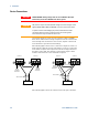
The following figures show how to connect two outputs in parallel.
The figure on the left illustrates local sensing. If voltage drop in the
load leads is a concern, the figure on the right shows how to connect
the sense leads directly at the load. Note that in both cases, the
remote sense terminals must be connected together.
The following figure shows the connections for 50A power modules.
OUTPUT 2 OUTPUT 1
+S + -S
LOAD
+S + -S
WITH LOCAL SENSING
+
OUTPUT 1
+S + -S
OUTPUT 2
+S + -S
WITH REMOTE SENSING
TWIST
LEADS
LOAD
+
SENSE
JUMPERS
INSTALLED
TWIST LEADS
SENSE
JUMPERS
INSTALLED
WITH LOCAL SENSING WITH REMOTE SENSING
SENSE
JUMPERS
INSTALLED
++
OUTPUT 1OUTPUT 3
LOAD
+
TWIST LEADS
+S +LS -LS -S
++
OUTPUT 1OUTPUT 3
LOAD
+
TWIST
LEADS
+S +LS -LS -S +S +LS -LS -S +S +LS -LS -S