
User`s guide


Installation 2
Series N6700 User’s Guide 37
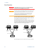
Open Sense Leads
The sense leads are part of the output's feedback path. Connect them
in such a way so that they do not inadvertently become open
circuited. The power system includes protection resistors that reduce
the effect of open sense leads during remote-sensing operation. If the
sense leads open during operation, the power system returns to the
local sensing mode, with the voltage at the output terminals
approximately 1% higher than the programmed value.
Over-voltage Protection Considerations
You must take into account any voltage drop in the load leads when
setting the over-voltage trip point. This is because the OVP circuit
senses at the output terminals and not at the sense terminals. Due to
the voltage drop in the load leads, the voltage sensed by the OVP
circuit could be higher than the voltage being regulated at the load.
Note that for Agilent Models N678xA SMU only, the OVP circuit
senses at the 4-wire sense terminals rather than at the output
terminals. This allows for more precise overvoltage monitoring
directly at the load. Since incorrect sense terminal wiring could
defeat this feature, there is also a backup local OVP function.
The local OVP function tracks the programmed OVP setting and trips
if the voltage at the + and - output terminals rises more than 1.5 V
above the programmed OVP setting. The local OVP also trips if the
voltage at the + and - output terminals exceeds 7.5 V on the 6 V range
and 21.5 V on the 20 V range.
Output Noise Considerations
Any noise picked up on the sense leads will appear at the output
terminals and may adversely affect CV load regulation. Twist the
sense leads or use a ribbon cable to minimize the pickup of external
noise. In extremely noisy environments it may be necessary to shield
the sense leads. Ground the shield at the power system end only; do
not use the shield as one of the sensing conductors.
The noise specifications documented in the Agilent N6700 Modular
Power System Family Specifications Guide apply at the output
terminals when using local sensing. However, voltage transients may
be produced at the load by noise induced in the leads or by load
current transients acting on the inductance and resistance of the load
lead. If it is desirable to keep voltage transient levels to a minimum,
place an aluminum or tantalum capacitor, with an approximate value
of 10 µF per foot (30.5 cm) of load lead, right across the load.