Agilent®1100 Series LC Devices Connecting the Hardware and Triggering Data Acquisition XCALI-97190 Revision B July 2007
© 2007 Thermo Fisher Scientific Inc. All rights reserved. Agilent® is a registered trademark of Agilent Technologies Inc. Hewlett-Packard® is a registered trademark of Hewlett-Packard Company. LCQ™, LTQ™, LXQ™, MSQ™, TSQ™, and Xcalibur™ are trademarks of Thermo Fisher Scientific Inc. Thermo Fisher Scientific Inc. provides this document to its customers with a product purchase to use in the product operation.
C Contents Preface . . . . . . . . . . . . . . . . . . . . . . . . . . . . . . . . . . . . . . . . . . . . . . . . . . . . . . . . . . . . . . .v About This Guide. . . . . . . . . . . . . . . . . . . . . . . . . . . . . . . . . . . . . . . . . . . . . . . . v Related Documentation . . . . . . . . . . . . . . . . . . . . . . . . . . . . . . . . . . . . . . . . . . . v Safety and Special Notices . . . . . . . . . . . . . . . . . . . . . . . . . . . . . . . . . . . . . . . . . v Safety Precautions. . . . . .
P Preface About This Guide This guide describes how to hardwire an Agilent® 1100 Series LC to a Thermo Scientific mass spectrometer and the data system computer, configure an Agilent autosampler for contact closure from within the Xcalibur Instrument Configuration program, and trigger data collection with an Agilent autosampler. This guide also describes how to upgrade a Hewlett-Packard® 1100 Series LC to an Agilent 1100 Series LC with Ethernet communication.
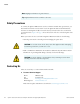
Preface Note Highlights information of general interest. Tip Helpful information that can make a task easier. Safety Precautions To connect the Agilent 1100 Series LC stack to a Thermo Scientific mass spectrometer, you must install an external contact board in one of the Agilent modules and a LAN interface board in a second Agilent module. To install a board, you must remove the cover from the optional board slot. Figure 2 on page 6 shows the location of the slot on the back panel of the detector.
Preface Y To contact Customer Service for ordering information Phone Fax Web site 800-532-4752 561-688-8731 www.thermo.com/finnigan Y To suggest changes to documentation or to Help • Fill out a reader survey online at www.thermo.com/lcms-techpubs. • Send an e-mail message to the Technical Publications Editor at techpubs.finnigan-lcms@thermofisher.com.
1 Agilent Modules Supported by LC Devices Versions 2.0.2 and 2.1.0 Table 1 lists the model number and firmware versions for the Agilent 1100 Series LC modules that are supported by the Xcalibur 2.0 and higher data system. Table 1. Xcalibur 2.0 supported firmware versions for the Agilent 1100 Series LC Module Model Number Firmware Version Binary pump G1312A A.06.01 (012) Quaternary pump G1311A A.06.01 (012) Autosampler G1313A A.06.01 (012) Thermostatted autosampler G1329A A.06.
1 Agilent Modules Supported by LC Devices Versions 2.0.2 and 2.1.0 Time Records Module Product Serial# Version Ready On-time EMF 4. Check the firmware versions of the Agilent 1100 Series modules. Refer to Table 1 for the firmware versions supported by the Xcalibur 2.0. and higher data system.
2 Connecting the Hardware This chapter describes how to install the interface boards, connect the Ethernet cables, and make the contact closure connections required to control an LC/MS system (Agilent LC/Thermo scientific MS) system from Xcalibur.
2 Connecting the Hardware Installing a Network Card in an Agilent Module Installing a Network Card in an Agilent Module For the Agilent LC system to communicate with the Xcalibur data system through an Ethernet connection, one of the modules in the Agilent 1100 Series LC stack must have a network interface card. If the stack has a detector, the card is usually installed in the detector. Tip Vendors label network cards with a unique MAC address, which is a 12-digit hexadecimal number.
2 Connecting the Hardware Installing a Network Card in an Agilent Module Y To install the network interface card in an Agilent module 1. Make sure the module (usually the detector) is turned off and unplugged from line power. Figure 1 shows the location of the power switches. When the power switch of a module is in the On position, the LED on the switch is green. When you turn the power switch of a module to the Off position, the LED turns off.
2 Connecting the Hardware Installing a Network Card in an Agilent Module 2. To prevent damage to the interface board, ensure that you are using ESD protection. For more information on preventing damage caused by an electric discharge, refer to the Reference Manual for the Agilent module. CAUTION To prevent damage to an instrument, always use ESD protection when handling electronic boards and components. 3.
2 Connecting the Hardware Connecting the Ethernet Communication Cables Connecting the Ethernet Communication Cables Y To connect the Ethernet communication cable to an Agilent 1100 Series LC 1. Connect a category 5, shielded Ethernet cable from the JetDirect 400N network card to the Ethernet switch. CAUTION To comply with safety and EMC regulations, you must use category 5, shielded Ethernet cables to make the Ethernet connections for your instrument. 2.
2 Connecting the Hardware Installing the External Contact Interface Board Installing the External Contact Interface Board If your Agilent 1100 Series Autosampler is not already equipped with an external contact interface board, install one as described below. Y To install the external contact interface board 1. If you have not already done so, turn off the autosampler and unplug it from line power. CAUTION To avoid electric shock, unplug the power cable that connects the Agilent module to line power.
2 Connecting the Hardware Connecting the Trigger Cable Connecting the Trigger Cable A trigger cable with a DB15 connector relays the start signal from the autosampler to the MS detector. Y To connect the trigger cable to the Agilent autosampler and the MS detector 1. If you have not already done so, install the external contact interface board as described in “Installing the External Contact Interface Board.” 2.
2 Connecting the Hardware Connecting the Trigger Cable Figure 5.
3 Configuring the Autosampler for Contact Closure The Agilent 1100 Series devices query the PC for the stack IP address only during their start up procedure. Therefore, complete the following procedure, and ensure that the Xcalibur Home Page window is open before you turn on the Agilent 1100 Series devices. Y To assign contact closure control to the Agilent 1100 Series autosampler 1. Choose Start > All Programs > Xcalibur > Instrument Configuration. The Instrument Configuration dialog box appears. 2.
3 Configuring the Autosampler for Contact Closure • In the Stack IP Address box, type the IP address for your Agilent 1100 LC stack. Leave the value set to the default or contact your network administrator for the IP address. The default stack IP address is 172-16-0-102. • In the Sub-mask box, type the subnet mask (address mask). Leave the subnet mask set to its default value, or contact your network administrator for the subnet mask. The default subnet mask value is 255-255-255-0.
4 Triggering Data Acquisition with the Autosampler If you want the Agilent 1100 series autosampler to trigger data acquisition, you must make the appropriate selections in the Timed Events page for the autosampler for each instrument method you create. Instrument methods contain the contact closure signals, the chromatographic conditions, and the MS detector settings for an LC/MS application. Note Configure the Agilent 1100 Series autosampler before performing the following procedure.
4 Triggering Data Acquisition with the Autosampler 7. Save your method with an appropriate name. 8. Choose File > Exit to close the Instrument Setup window. Xcalibur prompts you with the Save As dialog box, the File Summary Information Dialog box, and the File Save - Audit Trail dialog box.
5 Turning Off the Solvent Tracking Feature The solvent tracking feature on the Agilent 1100 LC pumps is not supported by Xcalibur at this time. You must turn off this feature to prevent error messages from terminating the data acquisition. Y To turn off the solvent tracking feature on the Agilent 1100 pump 1. If Xcalibur is open, close it. 2. Open the Analysis screen on the Agilent 1100 handheld control module. 3. Press the Settings button F1. Figure 8.
5 Turning Off the Solvent Tracking Feature 8. Press the Done button F6. 9. From the Windows XP start menu, choose All Programs > Xcalibur > Xcalibur. The Home Page appears. The Agilent 1100 devices should reconnect and appropriately display their status. 10. If the Info view is not displayed, choose View > Info View.
A Upgrading an HP 1100 Series LC The Xcalibur 2.0 and higher data system supports control of the Hewlett-Packard (HP) 1100 Series LC only if you upgrade the HP 1100 communication interface to an Ethernet interface. Y To upgrade your HP 1100 Series LC 1.
A Upgrading an HP 1100 Series LC Table 5. Parts required to upgrade an Xcalibur-controlled HP 1100 Series LC Part Number Description of Part 00825-01140 HP JetDirect 400N PCB 00012-70008 Ethernet 10 Base-T cable (2) 00825-01-00024 Ethernet switch 2. Follow the instructions in “Installing a Network Card in an Agilent Module” on page 4 to install the JetDirect 400N PCB.
I Index A J Agilent 1100 Series LC configuring autosampler for contact closure 11 external contact interface PCB, installing 8 solvent tracking feature, deactivating 15 supported mainboards for JetDirect cards 4 Agilent LAN interface board (G1369A) 5 JetDirect boards, supported 4 C S configuring the Agilent 1100 Series Autosampler 11 contact board 11 contact closure, configuring the Agilent Autosampler for 11 Contacting vi safety precautions vi slot cover, removing from an Agilent module vi solvent