
User manual


5-166 N9360A Multi UE Tester CDMA2000 User Manual
5 Description of Screens
Screen Field
Before starting the measurement, set the input items required
to execute tests, referring to the description shown in
Table 5-50.
* A changing magnification softkey is available. Refer to Storing Numeric Values on page 4-10 and Changing Magnification Softkey on
page 4-13.
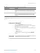
Configuration: Test Condition (Limit) Screen
The [Configuration: Test Condition(Limit)] screen is used to
define the test limits to judge Pass/Fail in Automatic Test,
Manual Test, and TX Analyzer modes. You can access to this
screen by pressing Limit softkey menu on the [Configuration:
Test Condition] screen. After pressing Limit softkey, the screen
shown as Figure 5-73 or Figure 3.74 appears in accordance with
the selected CDMA Mode (MC-1X or 1xEV-DO).
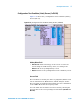
Configuration: Test Condition (Limit)Screen (MC-1x)
Figure 5-73 shows the [Configuration: Test Condition (Limit)]
Screen (MC-1x).
Table 5-50 Input field on the [Configuration: Test Condition (Loss)] screen
Input Field Description
Loss* Sets path losses generated by the coupler and cable used to connect mobile phones and radio signals
by band.
Select On or Off.
• On: Take coupling loss setting for RF In/Out into consideration. [Configuration: Select On to enable
the ATT setting change on the [Test Sequence] screen.
• Off: Do not take the setting into consideration for RF In/Out.
Set the loss for RF In and RF Out items as shown below according to the transmitter test and
receiver test.
• RF In: Set a traffic channel loss value for a transmitter test. The allowable range is between 0.0 and
99.9dB in 0.1 dB step.
• RF Out: Set a traffic channel loss value for a receiver test. The allowable range is between 0.0 and
99.9dB in 0.1 dB step.
There are some restrictions on the set value for Loss and ATT RF In/Out set on the [Test Sequence]
screen. Refer to Actual Input/Output Level and Correction on page 4-19.