
User manual


5-140 N9360A Multi UE Tester CDMA2000 User Manual
5 Description of Screens
Panel Key Restricts operation on the front panel of the tester.
Select either Lock or Unlock.
• Lock: Functions except Automatic test and Configuration are locked. Test Sequence, Test Condition
and File Management are not available in Configuration.
• Unlock: No operational restriction on the front panel of the tester.
Serial Port Sets the communication condition of the serial port (RS-232C) to use the external control. The option
E01 is required to use this function.
• Baud Rate: Set communication speed to 9600, 19200, 38400, 57600 or 115200 bit per second.
• Data Length: Set the data bit length to 7 or 8 bits.
• Stop Bits: Set the stop bit length to 1, 1.5 or 2 bits.
• Parity: Set the parity check mode to None, Odd or Even.
• Xcontrol: Set the flow control to None or Xon/Xoff.
Restart the tester after you have changed the setting of the serial port.
GP-IB
*
Sets various settings for external control via a GP-IB port. The option E02 is required to use this
function.
• Addr: Sets the address. The allowable range is from 1 to 15.
• EOI: Sets EOI control. Select On or Off.
• On: Enable EOI control. (Terminator setting is ignored.)
• Off: Disable EOI control. (Terminator setting is valid.)
Restart the tester after you have changed the setting of the GP-IB.
Terminator Sets the terminator of output text data to CR, LF or CR+LF. This is the setting for external control using
the serial interface, Ethernet and GP-IB. (The terminator of the input data is always LF.)
Printer Sets the destination to which the print data is sent when it is printed (when the Print Screen softkey is
pressed) to USB Memory or EPSON PM-G800.
• USB Memory: Saves the image of the screen on the USB memory. The file format is PNG (Portable
Network Graphics).
• EPSON PM-G800: Prints the hardcopy of the screen with the specified printer.
Beeper Sets beep.
Selects On or OFF.
• On: Beeps for each step of operation.
• OFF: Beeps only to indicate an error or warning.
MS EXT
Control Signal
Set control signals of the mobile phone.
• H/ L: Control signal-1 H/Control signal-2 L
• L/ H: Control signal-1 L/Control signal-2 H
• H/ H: Control signal-1 H/Control signal-2 H
• L/ L: Control signal-1 L/Control signal-2 L
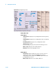
Table 5-40 Input items on the [Configuration] Screen
Input Field Description