
User manual


Screen Reference 5
N9360A Multi UE Tester W-CDMA User Manual 5-127
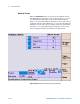
ACLR/OBW Option Installed
Table 5-39 describes measurement items of RF test in the TX
Analyzer test specified for the Tester which is equipped with
the Option W07. Refer to Table 5-39 for the remaining
measurement items.
NOTE
Refer to “Physical Channel Parameters of Signal Generator" on page D-2
about the parameters of physical channel transmitting in the Signal
Generator mode and receiving in the TX Analyzer mode.
For numeric value entry, the changing magnification softkey menu is
available. Refer to “Storing Numeric Values" on page 4-10 and “Changing
Magnification Softkey" on page 4-13.
The default state is the last setting stored in the internal memory of the
Tester before power off.
NOTE
Install the Option W07 when using the ACLR/OBW function.
Table 5-39 TX Analyzer Measurement Item (with Option W07)
Measurement Item Description
ACLR DSB 5 MHz Measures the sum of adjacent channel leakage
power at -5 MHz and +5 MHz.
ACLR DSB 10 MHz Measures the sum of adjacent channel leakage
power at -10 MHz and +10 MHz.
OBW Measures occupied bandwidth.
NOTE
ACLR DSB 5 MHz and ACLR DSB 10 MHz sum up the leakage power at
adjacent channels in upper side band and lower side band and
simultaneously measure them. Therefore, the leakage power in upper side
band and lower side band cannot be measured separately.
Table 5-40 Example of ACLR DSB Measurement Result
Result of
ACLR DSBACLR
Lower Side BandACLR Upper Side Band
32 dB --35 dB -35 dB