
User`s guide


Table Of Contents
- Overview
- Getting Started
- System Setting
- Making Measurements
- Measuring Multiple Signals
- Measuring a Low-Level Signal
- Improving Frequency Resolution and Accuracy
- Making Distortion Measurements
- One-button Power Measurement
- Making a Stimulus Response Transmission Measurement
- Measuring Stop Band Attenuation of a Low-pass Filter
- Making a Reflection Calibration Measurement
- Measuring Return Loss Using the Reflection Calibration Routine
- Making an Average Power Measurement
- Key Reference
- SCPI Command Reference
- Error Messages
- Menu Map
Making Measurements 4
N9340A User’s Guide 67
Making a Reflection Calibration Measurement
The following procedure makes a reflection
measurement using a coupler or directional bridge
to measure the return loss of a filter. This example
uses a 370 MHz low- pass filter as the DUT.
The calibration standard for reflection
measurements is usually a short circuit connected
at the reference plane (the point at which the
device under test (DUT) is connected.) See Figure
19. A short circuit has a reflection coefficient of 1
(0 dB return loss). It reflects all incident power
and provides a convenient 0 dB reference.
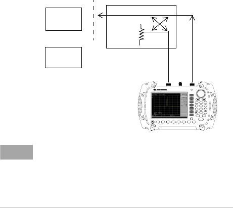
1 Connect the DUT to the directional bridge or
coupler as shown below. Terminate the
unconnected port of the DUT.
Figure 20 Reflection Measurement Short Calibration Test
Setup
N9340A
HANDHELD SPECTRUM ANALYZER
100 kHz - 3.0 GHz
PRESET
ENTER
FREQ SPANAMPTD
BW/
SWP
SYS MODE MEAS TRACE
ESC/ CLR
2DEF 3 GHI1 ABC
5MNO4JK L
6
PQR
8
VWX
7
STU
9
YZ_
0SAVE
LIM IT
MARK ER
Coupled
Port
Short
Circuit
DUT
Or
NOTE
If possible, use a coupler or bridge with the correct test
port connector types for both calibrating and measuring.
Adapters between the test port and DUT degrades
coupler/bridge directivity and system source match.
For best response, use the same adapter for the
calibration and the measurement. Terminate the second
port of a two port device.