
User`s guide


Table Of Contents
- Overview
- Getting Started
- System Setting
- Making Measurements
- Measuring Multiple Signals
- Measuring a Low-Level Signal
- Improving Frequency Resolution and Accuracy
- Making Distortion Measurements
- One-button Power Measurement
- Making a Stimulus Response Transmission Measurement
- Measuring Stop Band Attenuation of a Low-pass Filter
- Making a Reflection Calibration Measurement
- Measuring Return Loss Using the Reflection Calibration Routine
- Making an Average Power Measurement
- Key Reference
- SCPI Command Reference
- Error Messages
- Menu Map
4 Making Measurements
66 N9340A User’s Guide
Press [MEAS] > {Normalize} > {Store Ref} (1-> 4) >
{Normalize (On)}
8 Reconnect the DUT to the analyzer. Note that the
units of the reference level have changed to dB,
indicating that this is now a relative
measurement.
9 To change the normalized reference position:
Press [MEAS] > {Normalize} > {Norm Ref Posn} > {8} >
[ENTER]
10 Place the reference marker at the specified
cutoff frequency:
Press [MARKER] > {Normal} > {370} > MHz
11 Set the second marker as a delta frequency of
37 MHz:
Press {Delta} > 37 >MHz
12 In this example, the attenuation over this
frequency range is 19.16 dB/octave (one octave
above the cutoff frequency).
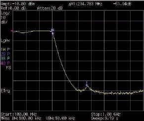
13 Use the front- panel knob to place the marker at
the highest peak in the stop band to determine
the minimum stop band attenuation. In this
example, the peak occurs at 600 MHz. The
attenuation is 51.94 dB.
Figure 19 Minimum Stop Band Attenuation