
User`s guide


Table Of Contents
- Overview
- Getting Started
- System Setting
- Making Measurements
- Measuring Multiple Signals
- Measuring a Low-Level Signal
- Improving Frequency Resolution and Accuracy
- Making Distortion Measurements
- One-button Power Measurement
- Making a Stimulus Response Transmission Measurement
- Measuring Stop Band Attenuation of a Low-pass Filter
- Making a Reflection Calibration Measurement
- Measuring Return Loss Using the Reflection Calibration Routine
- Making an Average Power Measurement
- Key Reference
- SCPI Command Reference
- Error Messages
- Menu Map
4 Making Measurements
64 N9340A User’s Guide
5 Press [Sweep] > {Sweep Time (Auto)} to put the
sweep time into stimulus response auto coupled
mode.
6 Increase measurement sensitivity and smooth the
noise:
Press [BW/SWP]> {RBW} >30 > {kHz}
Press [BW/SWP] > {VBW} > 30 > {kHz}
A decrease in the displayed amplitude is caused
by tracking error.
7 Connect the cable from the tracking generator
output to the analyzer input. Store the frequency
response in trace 4 and normalize:
Press [MEAS] > {Normalize} > {Store Ref} (1->4) >
{Normalize (On)}
8 Reconnect the DUT to the analyzer and change
the normalized reference position:
Press [MEAS] > {Normalize} > {Norm Ref Posn} > 8 >
[ENTER]
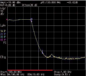
9 Measure the rejection of the low- pass filter:
Press [Marker] > {Normal} > 370 > MHz, {Delta} >
130 > {MHz}
The marker readout displays the rejection of the
filter at 130 MHz above the cutoff frequency of
the low- pass filter.
Figure 18 Measure the Rejection Range