
User`s guide
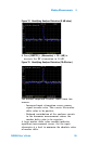


Table Of Contents
- Overview
- Getting Started
- System Setting
- Making Measurements
- Measuring Multiple Signals
- Measuring a Low-Level Signal
- Improving Frequency Resolution and Accuracy
- Making Distortion Measurements
- One-button Power Measurement
- Making a Stimulus Response Transmission Measurement
- Measuring Stop Band Attenuation of a Low-pass Filter
- Making a Reflection Calibration Measurement
- Measuring Return Loss Using the Reflection Calibration Routine
- Making an Average Power Measurement
- Key Reference
- SCPI Command Reference
- Error Messages
- Menu Map
Making Measurements 4
N9340A User’s Guide 55
Figure 14 Identifying Analyzer Distortion (O dB atten)
8 Press [AMPTD] > {Attenuation} > 10 > {dB} to
increase the RF attenuation to 10 dB.
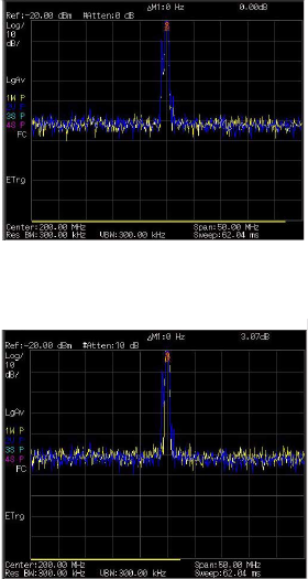
Figure 15 Identifying Analyzer Distortion (10 dB atten)
The marker amplitude readout comes from two
sources:
• Increased input attenuation causes poorer
signal- to- noise ratio. This causes the marker
delta value to be positive.
• Reduced contribution of the analyzer circuits
to the harmonic measurement causes the
marker delta value to be negative.
A large marker delta value readout indicates
significant measurement errors. Set the input
attenuator at a level to minimize the absolute value
of marker delta.