
User`s guide
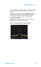


Table Of Contents
- Overview
- Getting Started
- System Setting
- Making Measurements
- Measuring Multiple Signals
- Measuring a Low-Level Signal
- Improving Frequency Resolution and Accuracy
- Making Distortion Measurements
- One-button Power Measurement
- Making a Stimulus Response Transmission Measurement
- Measuring Stop Band Attenuation of a Low-pass Filter
- Making a Reflection Calibration Measurement
- Measuring Return Loss Using the Reflection Calibration Routine
- Making an Average Power Measurement
- Key Reference
- SCPI Command Reference
- Error Messages
- Menu Map
4 Making Measurements
54 N9340A User’s Guide
3 Change the center frequency to the value of the
second (400MHz) harmonic:
• Press [MARKER] > {Peak Search}.
• Press [MARKER] > {Marker To} > {To Center}.
4 Change the span to 50 MHz and re- center the
signal:
• Press [SPAN] > 50 > {MHz}.
• Press [MARKER] > {Peak Search}.
5 Set the attenuation to 0 dB:
• Press [AMPTD] > {Attenuation} > 0 > {dB}.
• Press [MARKER] > {Marker To} > {To Ref}.
6 To determine whether the harmonic distortion
products are generated by the analyzer, first save
the trace data in trace 2 as follows:
• Press [TRACE] > {Trace (2)}.
• Press [TRACE] > {Clear Write}.
7 Allow trace 2 to update (minimum two sweeps),
then store the data from trace 2 and place a
delta marker on the harmonic of trace 2:
• Press [TRACE] > {View}.
• Press [MARKER] > {Peak Search}.
• Press [Marker] > {Delta}.
The figure below shows the stored data in trace 2
and the measured data in trace 1. The Marker
Delta indicator reads the difference in amplitude
between the reference and active trace markers.