
User`s guide
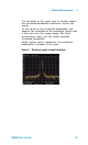


Table Of Contents
- Overview
- Getting Started
- System Setting
- Making Measurements
- Measuring Multiple Signals
- Measuring a Low-Level Signal
- Improving Frequency Resolution and Accuracy
- Making Distortion Measurements
- One-button Power Measurement
- Making a Stimulus Response Transmission Measurement
- Measuring Stop Band Attenuation of a Low-pass Filter
- Making a Reflection Calibration Measurement
- Measuring Return Loss Using the Reflection Calibration Routine
- Making an Average Power Measurement
- Key Reference
- SCPI Command Reference
- Error Messages
- Menu Map
Making Measurements 4
N9340A User’s Guide 53
Making Distortion Measurements
This section provides information on measuring
and identifying signal distortion.
Identifying Analyzer Generated Distortion
High level input signals may cause analyzer
distortion products that could mask the real
distortion present on the measured signal. Use
trace and the RF attenuator to determine which
signals, if any, may be internally generated
distortion products.
In this example, a signal from a signal generator is
used to determine whether the harmonic distortion
products are generated by the analyzer.
1 Input a signal (200 MHz, –10 dBm) to the
analyzer RF IN connector.
2 Set the analyzer center frequency and span:
• Press [PRESET]. (Factory Preset)
• Press [FREQ] > {Center Freq} > 400 > {MHz}.
• Press [SPAN] > 700 > {MHz}.
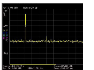
The signal produces harmonic distortion products
(spaced every 200 MHz from the original 200 MHz
signal)
Figure 13 Harmonic distortion