
User`s guide
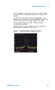


Table Of Contents
- Overview
- Getting Started
- System Setting
- Making Measurements
- Measuring Multiple Signals
- Measuring a Low-Level Signal
- Improving Frequency Resolution and Accuracy
- Making Distortion Measurements
- One-button Power Measurement
- Making a Stimulus Response Transmission Measurement
- Measuring Stop Band Attenuation of a Low-pass Filter
- Making a Reflection Calibration Measurement
- Measuring Return Loss Using the Reflection Calibration Routine
- Making an Average Power Measurement
- Key Reference
- SCPI Command Reference
- Error Messages
- Menu Map
4 Making Measurements
52 N9340A User’s Guide
Improving Frequency Resolution and Accuracy
Using the frequency counter to improve frequency
resolution and accuracy.
1 Press [PRESET]. (Factory Preset)
2 Input a signal (1 GHz, –30 dBm) to the
analyzer’s RF IN connector.
3 Set the center frequency to 1 GHz and the span
to 5 MHz:
4 Press [MARKER] > {More (1 of 2)} > {Mode} > {Freq
Count} to turn the frequency counter on.
5 Move the marker by rotating the knob, to a point
half- way down the skirt of the signal response.
6 Press [MARKER] > {More (1 of 2)} > {Mode} >
{Normal} to turn off the marker counter.
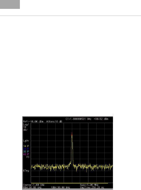
Figure 12 Using the frequency counter
NOTE
Marker count will properly function only on CW signals or
discrete spectral components. The marker must be > 40
dB above the displayed noise level.