
User`s guide


Table Of Contents
- Overview
- Getting Started
- System Setting
- Making Measurements
- Measuring Multiple Signals
- Measuring a Low-Level Signal
- Improving Frequency Resolution and Accuracy
- Making Distortion Measurements
- One-button Power Measurement
- Making a Stimulus Response Transmission Measurement
- Measuring Stop Band Attenuation of a Low-pass Filter
- Making a Reflection Calibration Measurement
- Measuring Return Loss Using the Reflection Calibration Routine
- Making an Average Power Measurement
- Key Reference
- SCPI Command Reference
- Error Messages
- Menu Map
1 Getting Started
22 N9340A User’s Guide
Viewing a Signal on the Analyzer
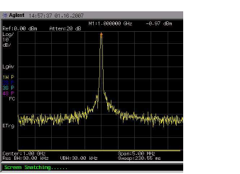
1 Using an RF signal generator to provide a CW
signal of 1.0 GHz, at a power level of 0.0 dBm.
2 Press [SYS] > {More} > {Preset} and select Default to
toggle the preset settings to default,
factory- defined status.
3 Press the green [Preset] key to restore the
analyzer measurement settings to factory
defaults.
4 Connect the RF OUT of the generator to the
analyzer’s RF IN connector.
5 Press [FREQ] > {Center Freq} > 1> {GHz} to set the
analyzer center frequency to 1 GHz.
6 Press [SPAN] > 5 > {MHz} to set the analyzer fre-
quency span to 5 MHz.
7 Press [MARKER] > {Peak Search} > {Peak} to place a
marker (M1) at the highest peak (1 GHz) on the
display.
The Marker amplitude and frequency values appear
in the function block and in the upper- right corner
of the screen.
Use the front- panel knob, arrow keys, or the soft-
keys in the Peak Search menu to move the marker
and read out the value of both the frequency and
amplitude displayed on the screen.
Figure 1 View a signal (1 GHz, 0 dBm)