
User`s guide


Table Of Contents
- Overview
- Getting Started
- System Setting
- Making Measurements
- Measuring Multiple Signals
- Measuring a Low-Level Signal
- Improving Frequency Resolution and Accuracy
- Making Distortion Measurements
- One-button Power Measurement
- Making a Stimulus Response Transmission Measurement
- Measuring Stop Band Attenuation of a Low-pass Filter
- Making a Reflection Calibration Measurement
- Measuring Return Loss Using the Reflection Calibration Routine
- Making an Average Power Measurement
- Key Reference
- SCPI Command Reference
- Error Messages
- Menu Map
1 Getting Started
18 N9340A User’s Guide
Powering on the Analyzer for the First Time
The N9340A is fitted with a transflective screen,
which is viewable under all lighting conditions.
In bright lighting conditions, the display is brighter
and easier to read when you allow light to fall
directly on the screen.
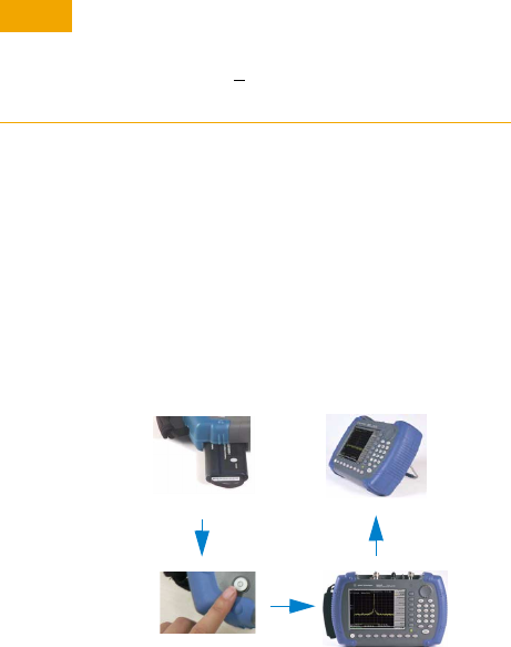
Power on your N9340A
Insert the battery into the analyzer or connect the
analyzer to an external line power supply via the
AC- DC adapter, then press the power switch on
the front panel of your N9340A to power on the
analyzer.
Allow the analyzer to warm- up for 30 minutes
before making a calibrated measurement. To meet
its specifications, the analyzer must meet operating
temperature conditions.
CAU-CAUTION
Use only the original AC-DC adapter or originally supplied
battery for the power source.
The maximum RF input level of an average continuous
power is 33 dBm (or +
50 VDC signal input). Avoid
connecting a signal into the analyzer that exceeds the
maximum level.
Use
Tilt Stand
Install
battery
Press
Power
Switch