
User`s guide
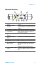


Table Of Contents
- Overview
- Getting Started
- System Setting
- Making Measurements
- Measuring Multiple Signals
- Measuring a Low-Level Signal
- Improving Frequency Resolution and Accuracy
- Making Distortion Measurements
- One-button Power Measurement
- Making a Stimulus Response Transmission Measurement
- Measuring Stop Band Attenuation of a Low-pass Filter
- Making a Reflection Calibration Measurement
- Measuring Return Loss Using the Reflection Calibration Routine
- Making an Average Power Measurement
- Key Reference
- SCPI Command Reference
- Error Messages
- Menu Map
Overview 1
N9340A User’s Guide 5
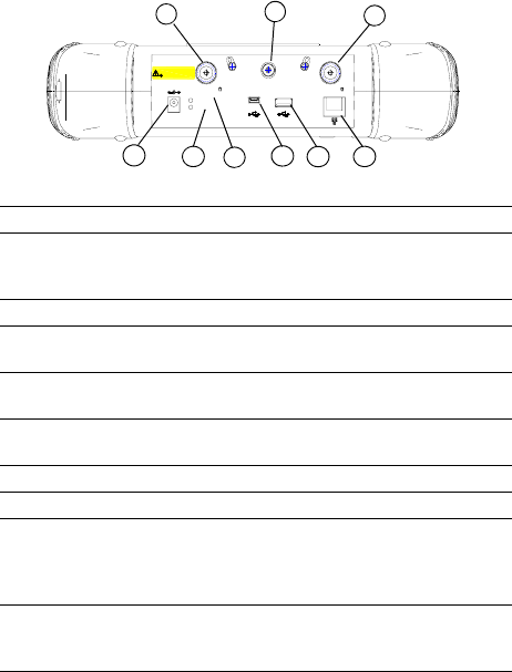
Top Panel Overview
PC
Ext. Pow er
12-18
VDC
80 W MAX
Char gi ng
RF INPUT 50 RF OU T 50
EXT TRIG IN/
EXT REF I N
50 VDC MAX
33
dBm (2 W) MAX
1
2
8
3
4
5
6
7
9
Caption Function
1External DC power
connector
Provides input for the DC power source via
an AC-DC adapter, or Automotive type DC
adapter.
2 LED indicator (Charging) Lights (On) when the battery is charging
3 LED indicator Lights (On) when external DC power is
connected to the tester
4USB interface Type B
(Device)
Connects to a PC
5USB interface Type A
(Host)
Connects to a USB memory stick or disk
6 LAN Interface (Reserved for future expansion)
7 RF OUT Connector (Reserved for future expansion)
8 EXT TRIG IN/REF IN
(BNC, Female)
Connects to an external TTL signal or a 10
MHz reference signal. The TTL signal is
used to
trigger the analyzer’s internal sweep
9 RF IN Connector (Type N,
Female)
Accepts an external input with a frequency
range from 100 kHz to 3 GHz, tunable to 9
kHz.