
User`s guide

N9340A Overview 1
N9340A User’s Guide 11
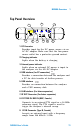
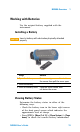
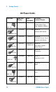
Top Panel Overview
PC
Ext. Po w er
12-18
VD C
80 W MAX
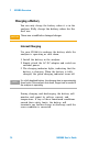
Char ging
RF INPUT 50 RF O U T 5 0
EXT TRIG IN/
EXT REF IN
50 VD C MAX
33
dBm (2 W) MAX
1
2
8
3
4
5 6
7
9
12-18 VDC
55W MAX
1. DC Connector
Provides input for the DC power source via an
AC- DC adapter. Make sure that the line- power
source outlet has a protective ground contact.
2. Charging indicator
Lights when the battery is charging.
3. External power indicator
Lights when an external DC power is input to
the analyzer via the AD- DC adapter.
4. USB interface (for PC connection)
Provides a connection between the analyzer and
a PC for data transfer of further process.
5. USB interface
Provides an connection between the analyzer
and a USB memory disk.
6. LAN Interface (For future expansion)
7. RF OUT Connector (For future expansion)
8. EXT TRIG IN/REF IN (BNC, Female)
Connects to an external TTL signal or a 10 MHz
reference signal. The TTL signal is used to
trigger the analyzer’s internal sweep.
9. RF IN Connector (Type N, Female)
Accepts an external input with a frequency
ranges from 100 kHz to 3 GHz.
PC