
User`s guide

Making Measurements 4
N9340B User’s Guide 59
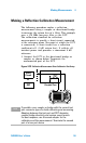
Making a Reflection Calibration Measurement
The following procedure makes a reflection
measurement using a coupler or directional bridge
to measure the return loss of a filter. This example
uses a 370 MHz low- pass filter as the DUT.
The calibration standard for reflection
measurements is usually a short circuit connected
at the reference plane (the point at which the DUT
is connected). A short circuit has a reflection
coefficient of 1 (0 dB return loss). It reflects all
incident power and provides a convenient 0 dB
reference.
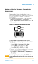
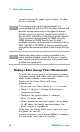
1 Connect the DUT to the directional bridge or
coupler as shown below. Terminate the
unconnected port of the DUT.
Figure 4-20 Reflection Measurement Short Calibration Test Setup
N9340A
HANDHELD SPECTRUM ANALYZER
100 kHz - 3.0 GHz
PRESET
ENTER
FREQ SPANAMPTD
BW/
SWP
SYS MODE MEAS TRACE
ESC/ CLR
2DEF 3 GHI1 ABC
5MNO4JK L
6
PQR
8
VWX
7
STU
9
YZ_
0SAVE
LIM IT
MARK ER
Coupled Port
Short
Circuit
DUT
or
NOTE
If possible, use a coupler or bridge with the correct test
port connector types for both calibrating and measuring.
Adapters between the test port and DUT degrades
coupler/bridge directivity and system source match.
For best response, use the same adapter for the
calibration and the measurement. Terminate the second
port of a two port device.