
User`s guide

Overview 1
N9340B User’s Guide 7
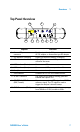
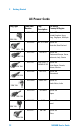
Top Panel Overview
PC
12-18 VDC
55W M AX
50 VDC MA X
33
dBm (2 W) MAX
RF IN PUT 50 RF OU T 50
EXT TRIG IN/
EXT REF IN
Ext . Power
Charging
1
2
9
3
4
5
7
8
10
6
Caption Function
1 External DC power
connector
Provides input for the DC power source via an
AC-DC adapter, or Automotive type DC adapter.
2 LED indicator (Charging) Lights (On) when the battery is charging
3 LED indicator Lights (On) when external DC power is con-
nected to the tester
4 USB interface (Device) Connects to a PC
5 USB interface (Host) Connects to a USB memory stick or disk
6 Headphone Connects to a headphone
7 LAN Interface Connects to a PC for SCPI remote control
8 RF OUT Connector The output for the built-in tracking generator.
Enabled with Option TG3.
9 EXT TRIG IN/REF IN
(BNC, Female)
Connects to an external TTL signal or a 10 MHz
reference signal. The TTL signal is used to
trigger the analyzer’s internal sweep
10 RF IN Connector (50 Ω) Accepts an external input with a frequency range
from 100 kHz to 3 GHz, tunable to 9 kHz.