
Technical data


28 Agilent N8211A/N8212A Performance Upconverter Synthetic Instrument Module, 250 kHz to 20/40 GHz
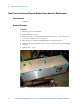
3 Battery Removal/Replacement
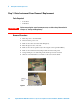
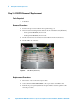
Step 3. A18 CPU Removal/Replacement
Tools Required
• T-10 driver
Removal Procedure
1 Position the upconverter with the front panel facing you.
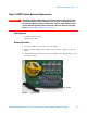
2 Disconnect the following ribbon cables from the A18 CPU board (#5 arrow):
• W29 (p/n N8210-60202) from A18 J1
• W30 (p/n N8210-60203) from A18 J2
3 Lift the retention levers and disconnect the CPU from the motherboard.
4 Lift the CPU out of the slot.
Figure 4 CPU Board (#5 arrow)
Replacement Procedure
1 Reverse the order of the removal procedure.
2 Send command "DIAG:FILE:REST", this copies data to the CPU board.
3 Perform the post-repair adjustments and performance tests that pertain to this
removal procedure.