
Technical data


Battery Removal/Replacement 3
Agilent N8211A/N8212A Performance Upconverter Synthetic Instrument Module, 250 kHz to 20/40 GHz 27
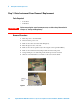
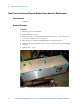
Bottom Cover
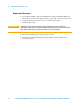
Remove four screws (p/n 0515-1521) and remove the cover. See Figure 3.
Figure 3 Instrument Inner Bottom Cover Screw Location
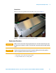
Replacement Procedure
• Reverse the order of the removal procedures.
• Torque all T-10 screws to 9-inch pounds.
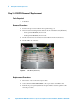
CAUTION
Make sure that the brown orange cable (W13) sits in the relief slot of the top cover,
but does not sit above the surface. The relief slot is located under the cable routing
label.
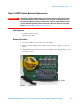
CAUTION
Position the internal top cover on the instrument making sure that the grey flex
cable sits properly in the slot. See arrow in Figure 2.