
Technical data


26 Agilent N8211A/N8212A Performance Upconverter Synthetic Instrument Module, 250 kHz to 20/40 GHz
3 Battery Removal/Replacement
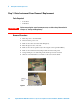
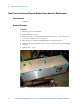
Step 2. Inner Instrument Top and Bottom Cover Removel/Replacement
Tools Required
• T-10 driver
Removal Procedure
Top Cover
1 Turn off power to the instrument.
2 Disconnect the power cord.
3 Remove the outer cover from the upconverter. Refer to “Step 1. Outer Instrument
Cover Removel/Replacement" on page 24.
4 Place the upconverter flat and upright with the front panel facing you.
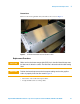
5 Remove four screws (p/n 0515-1521) on the sides, and five screws (p/n 0515-0430)
on the top.
6 Remove the top cover.
Figure 2 Instrument Inner Top Cover Screw Location