
Technical data


24 Agilent N8211A/N8212A Performance Upconverter Synthetic Instrument Module, 250 kHz to 20/40 GHz
3 Battery Removal/Replacement
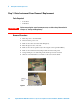
Step 1. Outer Instrument Cover Removel/Replacement
Tools Required
• T-15 driver
• T-20 driver
Removal Procedure
1 Turn off power to the instrument.
2 Disconnect the power cord.
3 Remove the four bottom feet and locking keys.
4 Place the upconverter on its side.
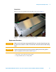
5 Remove the four rear panel feet by removing the screws (p/n 0515-0619).
6 Remove the Coherent Carrier jumper cables from the front panel.
7 Using a thick piece of cushioning foam, tilt the upconverter forward.
8 Slide the outer instrument cover back to remove it from the frame.
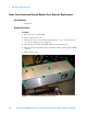
Figure 1 Instrument Cover Removal
WARNING
Before removing the outer instrument cover, read the safety information in
Chapter 2, “Safety and Regulatory”.