Agilent N8211A/N8212A Performance Upconverter Synthetic Instrument Module, 250 kHz to 20/40 GHz Security Features Guide Edition, April 20, 2007 Agilent Technologies
Notices © Agilent Technologies, Inc. 2007 Manual Part Number No part of this manual may be reproduced in any form or by any means (including electronic storage and retrieval or translation into a foreign language) without prior agreement and written consent from Agilent Technologies, Inc. as governed by United States and international copyright laws. N8212-90007 Edition Edition, April 20, 2007 Printed in USA Windows® Agilent Technologies, Inc.
Introducing the N8211A/N8212A Performance Upconverter The Agilent Technologies N8211A/N8212A performance upconverter are fully synthesized 20 or 40 GHz synthetic instrument modules that convert a baseband signal to a microwave signal. Agilent's synthetic instrument family offers the highest-performing RF/MW LAN-based modular instrumentation and the smallest footprint for automated test systems (ATSs); providing the maximum flexibility and minimizing the cost of an ATS over its lifetime.
Agilent N8211A/N8212A Performance Upconverter Synthetic Instrument Module, 250 kHz to 20/40 GHz
Security Features Guide 1 Security Features “Using Security Functions" on page 6 “Upconverter Memory" on page 7 “Removing Persistent State Information Not Removed During Erase" on page 13 “User IQ Cal File (Vector Models Only)" on page 14 “SCPI Commands" on page 15 Agilent Technologies 5
1 Security Features Using Security Functions This document describes how to use the security functions of the N8211A performance analog upconverter and N8212A performance vector upconverter to protect and remove classified proprietary information stored or displayed in the instrument. The information in this document is presented with the assumption that you are familiar with the basic operation of the upconverter.
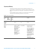
Security Features 1 Upconverter Memory The N8211A performance analog upconverter and N8212A performance vector upconverter have several memory types, each used for storing a specific types of data. Before removing sensitive data, it is important to understand how each memory type is used. The following tables describe each memory type used in the N8211A performance analog upconverter and N8212A performance vector upconverter.
1 Security Features Table 1: Base Instrument Memory (continued) Memory Type and Size Writable During Normal Operation? Data Retained When Powered Off? Purpose/Contents Data Input Method Location in Instrument and Remarks Firmware Memory (Flash) 12 MB No Yes main firmware image factory installed or firmware upgrade CPU board (same chip as main flash memory, but managed separately) During normal operation, this memory cannot be overwritten except for LAN configuration.
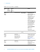
Security Features 1 Table 1: Base Instrument Memory (continued) Data Retained When Powered Off? Purpose/Contents Data Input Method Location in Instrument and Remarks Calibration No Backup Memory (Flash) 512 KB Yes factory calibration/configurati on data backup no user data factory or service only motherboard Boards Memory (Flash) 512 Bytes No Yes factory calibration and information files, code images, and self-test limits no user data factory or service only All RF boards, baseband generator
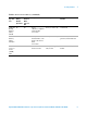
1 Security Features Removing Sensitive Data from Memory This section describes several security functions that can be used to remove sensitive data stored in the N8211A performance analog upconverter and N8212A performance vector upconverter when moving them from a secure development environment. NOTE All security functions described in this section have an equivalent SCPI command for remote operation.
Security Features 1 Additional Procedures The following procedures offer additional security details. Erase All This function removes all user files, user flatness calibrations, user I/Q calibrations, and resets all table editors with original factory values, ensuring that user data and configurations are not accessible or viewable. The instrument appears as if it is in its original factory state, however, the memory is not sanitized.
1 Security Features Erase and Overwrite All This function performs the same actions as Erase All and then clears and overwrites the various memory types in accordance with Department of Defense (DoD) standards as described below. SRAM All addressable locations are overwritten with random characters. CPU Flash All addressable locations are overwritten with random characters and then the flash blocks are erased.
Security Features 1 Removing Persistent State Information Not Removed During Erase Persistent State The persistent state settings contain instrument setup information that can be toggled within predefined limits such as display intensity, contrast, and the LAN address. In vector models, the user IQ Cal is also saved in this area.
1 Security Features User IQ Cal File (Vector Models Only) When a user-defined IQ calibration has been performed, the cal file data is removed by setting the cal file to default, as follows: Send these commands to the N8211A or N8212A upconverter: CAL:IQ:DEF CAL:WBIQ:DEF If Your Instrument is Not Functioning If the instrument is not functioning and you are unable to use the security functions, you may physically remove the processor board and hard disk, if installed, from the instrument.
Security Features 1 SCPI Commands Security Commands :SECurity:ERASeall :SYSTem:SECurity:ERASall This command removes all user files, table editor files, flatness correction files, and baseband generator files. This command differs from the :DELete:ALL command, which does not remove table editor files. :SECurity:LEVel NONE|ERASe|OVERwrite|SANitize :SYSTem:SECurity:LEVel NONE|ERASe|OVERwrite|SANitize :SYSTem:SECurity:LEVel? This command selects the secure mode and enables you to select a level of security.
1 Security Features Remarks You can exit the secure mode by entering :SYST:SECUrity:LEVel NONE, or by cycling the power. :SECurity:OVERwrite :SYSTem:SECurity:OVERwrite This command removes all user files, table editor files, flatness correction files, and baseband generator files. The memory is then overwritten with random data as follows: • SRAM All addressable locations will be overwritten with random characters. • HARD DISK All addressable locations will be overwritten with random characters.
Security Features 1 Memory Subsystem Commands :CATalog:BINary :MEMory:CATalog:BINary? This command outputs a list of the binary files. The return data will be in the following form: ,{,""} The upconverter will return the two memory usage parameters and as many file listings as there are files in the directory list.
1 Security Features :CATalog[:ALL] :MEMory:CATalog[:ALL]? This command outputs a list of all files in the memory subsystem, but does not include files stored on the Option 002/602 baseband generator. The return data is in the following form: ,{,""} The upconverter returns the two memory usage parameters and as many file listings as there are files in the memory subsystem.
2 Safety and Regulatory “General Safety Considerations" on page 20 “Lithium Battery Disposal" on page 21 “Assistance" on page 21 “Certification" on page 21 The following safety notes are used throughout this manual. Familiarize yourself with each of the notes and its meaning before operating this instrument. CAUTION Caution denotes a hazard. It calls attention to a procedure that, if not correctly performed or adhered to, would result in damage to or destruction of the product.
2 Safety and Regulatory General Safety Considerations The following safety notes apply specifically to upconverters. These notes also appear in other chapters of this service guide as required. 20 WA R N I N G These servicing instructions are for use by qualified personal only. To avoid electrical shock, do not perform any servicing unless you are qualified to do so. WA R N I N G The opening of covers or removal of parts is likely to expose dangerous voltages.
2 Safety and Regulatory Lithium Battery Disposal When the battery on the A18 CPU is exhausted and/or ready for disposal, dispose of it according to your country’s requirements. You can return the battery to your nearest Agilent Technologies Sales and Service office for disposal, if required. Assistance Product maintenance agreements and other customer assistance agreements are available for Agilent Technologies products.
2 22 Safety and Regulatory Agilent N8211A/N8212A Performance Upconverter Synthetic Instrument Module,
Security Features Guide 3 Battery Removal/Replacement “Step 1. Outer Instrument Cover Removel/Replacement" on page 24 “Step 1. Outer Instrument Cover Removel/Replacement" on page 24 “Step 2. Inner Instrument Top and Bottom Cover Removel/Replacement" on page 26 “Step 3. A18 CPU Removal/Replacement" on page 28 “Step 4.
3 Battery Removal/Replacement Step 1. Outer Instrument Cover Removel/Replacement Tools Required • T-15 driver • T-20 driver WA R N I N G Before removing the outer instrument cover, read the safety information in Chapter 2, “Safety and Regulatory”. Removal Procedure 1 Turn off power to the instrument. 2 Disconnect the power cord. 3 Remove the four bottom feet and locking keys. 4 Place the upconverter on its side. 5 Remove the four rear panel feet by removing the screws (p/n 0515-0619).
Battery Removal/Replacement 3 Replacement Procedure CAUTION When sliding the instrument cover on, make sure that you do not catch the edge of the RF shield on the rear panel, also make sure that the grey cable is not sticking out of the inner top cover slot. • Reverse the order of the removal procedures. • Torque all T-15 screws to 21-inch pounds. • Torque all T-20 screws to 21-inch pounds.
3 Battery Removal/Replacement Step 2. Inner Instrument Top and Bottom Cover Removel/Replacement Tools Required • T-10 driver Removal Procedure Top Cover 1 Turn off power to the instrument. 2 Disconnect the power cord. 3 Remove the outer cover from the upconverter. Refer to “Step 1. Outer Instrument Cover Removel/Replacement" on page 24. 4 Place the upconverter flat and upright with the front panel facing you. 5 Remove four screws (p/n 0515-1521) on the sides, and five screws (p/n 0515-0430) on the top.
Battery Removal/Replacement 3 Bottom Cover Remove four screws (p/n 0515-1521) and remove the cover. See Figure 3. Figure 3 Instrument Inner Bottom Cover Screw Location Replacement Procedure CAUTION Make sure that the brown orange cable (W13) sits in the relief slot of the top cover, but does not sit above the surface. The relief slot is located under the cable routing label. CAUTION Position the internal top cover on the instrument making sure that the grey flex cable sits properly in the slot.
3 Battery Removal/Replacement Step 3. A18 CPU Removal/Replacement Tools Required • T-10 driver Removal Procedure 1 Position the upconverter with the front panel facing you. 2 Disconnect the following ribbon cables from the A18 CPU board (#5 arrow): • W29 (p/n N8210-60202) from A18 J1 • W30 (p/n N8210-60203) from A18 J2 3 Lift the retention levers and disconnect the CPU from the motherboard. 4 Lift the CPU out of the slot.
Battery Removal/Replacement 3 Step 4. A18BT1 Battery Removal/Replacement WA R N I N G This battery contains lithium. Do not incinerate or puncture this battery. Do not install this battery backwards. Dispose of the battery in a safe manner and in accordance with your country's requirements. You can return batteries to your nearest Agilent Technologies Sales and Service office for disposal, if required. Refer to “Lithium Battery Disposal" on page 21.
3 Battery Removal/Replacement Replacement Procedure 1 To install the A18BT1 3 V, 0.16 A Lithium battery with p/n 1420-0314 (Panasonic BR 2325), the positive side is aligned with the positive sign on the A18’s battery clip. 2 Apply the tape that was removed or a non-conductive tape such as Permacel Capcom tape. CAUTION Apply tape over the battery to keep it from shaking free during instrument movement.