
Technical data

Using the STATus System 27
Agilent N8201A Performance Downconverter Synthetic Instrument Module, 250 kHz to 26.5 GHz 549
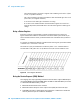
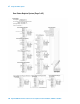
To query the status byte register, send the command *STB? The response will be the
decimal sum of the bits which are set to 1. For example, if bit number 7 and bit number 3 are
set to 1, the decimal sum of the 2 bits is 128 plus 8. So the decimal value 136 is returned.
The *STB command does not clear the status register
In addition to the status byte register, the status byte group also contains the service
request enable register. This register lets you choose which bits in the status byte register
will trigger a service request.
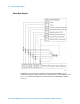
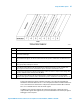
Bit Description
0, 1 These bits are always set to 0.
2 A 1 in this bit position indicates that the SCPI error queue is not empty which means that it contains at
least one error message.
3 A 1 in this bit position indicates that the data questionable summary bit has been set. The data
questionable event register can then be read to determine the specific condition that caused this bit to be
set.
4 A 1 in this bit position indicates that the instrument has data ready in the output queue. There are no lower
status groups that provide input to this bit.
5 A 1 in this bit position indicates that the standard event summary bit has been set. The standard event
status register can then be read to determine the specific event that caused this bit to be set.
6 A 1 in this bit position indicates that the instrument has at least one reason to report a status change. This
bit is also called the master summary status bit (MSS).
7 A 1 in this bit position indicates that the standard operation summary bit has been set. The standard
operation event register can then be read to determine the specific condition that caused this bit to be set.