
Technical data


284 Agilent N8201A Performance Downconverter Synthetic Instrument Module, 250 kHz to 26.5 GHz
15 Measurement Setup
x dB
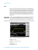
Enables you to specify the power level used to determine the emission bandwidth as the
number of dB down from the highest signal point (P1), within the occupied bandwidth span.
This function is an independent calculation from the OBW calculation. The x dB bandwidth
result is also called the emissions bandwidth, or EBW. This will set arrow markers (f1 and
f2) to your specified dB value below the maximum power and compute the total power
between those arrows. Frequencies f1 and f2 are determined as the furthest frequencies x
dB below and above P1, respectively. The emission bandwidth is then calculated as f2 - f1
as shown by the arrows indicated in Figure 8 (note that the diamond markers are for the
OBW function).
Figure 8 Occupied Bandwidth Measurement Results
Key Path: Meas Setup
State Saved: Saved in Instrument State.
Factory Preset: –26 dB
Default Terminator: dB
NOTE
The asterisk next to the x dB bandwidth value in Figure 8 indicates the results may not have
been determined with optimal N8201A settings. If emission bandwidth is your primary
interest, select Meas Setup, Max Hold. Then change detector mode to peak by pressing
Det/Demod, Detector, Peak. Acquiring peak data ensures accuracy of this measurement.