
Technical data


Det/Demod 5
Agilent N8201A Performance Downconverter Synthetic Instrument Module, 250 kHz to 26.5 GHz 107
The detector in use is indicated on the left side of the display, just below Reference level.
The designators are:
• Norm - Normal detector
• Avg - Average detector
• Peak - Peak detector
• Samp - Sample detector
• NPk - Negative Peak detector
• EmiQP - Quasi Peak detector
• EmiAv - EMI Average detector
• EmiPk - Peak detector with CISPR bandwidths
• MILPk - Peak detector with MIL bandwidths
If the detector has been manually selected, a “#” appears next to it.
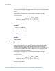
When discussing detectors, it is important to understand the concept of a trace “bucket.”
For every trace point displayed in swept and zero-span analysis, there is a finite time during
which the data for that point is collected. The N8201A has the ability to look at all of the
data collected during that time and present a single point of trace data based on the
detector mode. We call the interval during which the data for that trace point is being
collected, the “bucket.” The data is sampled rapidly enough within a “bucket” that it must
be reduced in some fashion to yield a single data point for each bucket. There are a number
of ways to do this and which way is used depends on the detector selected. Details on how
each detector does this are presented below.
In FFT analysis, the bucket represents just a frequency interval. The detector in an FFT mode
determines the relationship between the spectrum computed by the FFT and the single data
point displayed for the bucket.
Tip: RMS Detection
To measure the average power (RMS voltage) in each display point, set Detector to
Average, and verify that Avg/VBW Type is set to Pwr Avg (RMS).
Key Path: Det/Demod
State Saved: Saved in Instrument State
Factory Preset:
Normal, Auto Coupled
Remote Command:
[:SENSe]:DETector[:FUNCtion]
NORMal|AVERage|POSitive|SAMPle|NEGative|QPEak|EAVerage|EPOSitive|MPOSitiv|
RMS