
Technical data


120 Agilent N8211A/N8212A Performance Upconverter Synthetic Instrument Module, 250 kHz to 20 / 40 GHz
4 Programming the Status Register System
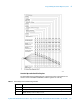
Table 8 Data Questionable Power Condition Register Bits
Data Questionable Power Transition Filters (negative and positive)
The Data Questionable Power Transition Filters specify which type of bit state changes in
the condition register set corresponding bits in the event register. Changes can be positive
(0 to 1) or negative (1 to 0).
Data Questionable Power Event Register
The Data Questionable Power Event Register latches transition events from the condition
register as specified by the transition filters. Event registers are destructive read-only.
Reading data from an event register clears the content of that register.
Bit Description
0 Reverse Power Protection Tripped. A 1 in this bit position indicates that the reverse power protection
(RPP) circuit has been tripped. There is no output in this state. Any conditions that may have caused
the problem should be corrected. Reset the RPP circuit by sending the remote SCPI command:
OUTput:PROTection:CLEar. Resetting the RPP circuit bit, resets this bit to 0.
1 Unleveled. A 1 in this bit position indicates that the output leveling loop is unable to set the output
power.
2 IQ Mod Overdrive. Always 0.
3 Lowband Detector Fault. A 1 in this bit position indicates that the lowband detector heater circuit has
failed.
4−14 Unused. These bits are always set to 0.
15 Always 0.
Query: STATus:QUEStionable:POWer:CONDition?
Response: The decimal sum of the bits set to 1.
Commands: STATus:QUEStionable:POWer:NTRansition <value> (negative transition),
or STATus:QUEStionable:POWer:PTRansition <value> (positive
transition), where
<value> is the sum of the decimal values of the bits you want to enable.
Queries: STATus:QUEStionable:POWer:NTRansition?
STATus:QUEStionable:POWer:PTRansition?
Query: STATus:QUEStionable:POWer[:EVENt]?