
Technical data


114 Agilent N8211A/N8212A Performance Upconverter Synthetic Instrument Module, 250 kHz to 20 / 40 GHz
4 Programming the Status Register System
Standard Operation Transition Filters (negative and positive)
The Standard Operation Transition Filters specify which types of bit state changes in the
condition register set corresponding bits in the event register. Changes can be positive (0 to
1) or negative (1 to 0).
Standard Operation Event Register
The Standard Operation Event Register latches transition events from the condition register
as specified by the transition filters. Event registers are destructive read only. Reading data
from an event register clears the content of that register.
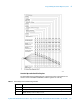
3 Sweeping. A 1 in this bit position indicates that a sweep is in progress.
4 Measuring. Always 0.
5 Waiting for Trigger. A 1 in this bit position indicates that the source is in a “wait for trigger”
state.
6,7,8 Unused. These bits are always set to 0.
9 Always 0.
10 Always 0.
11 Sweep Calculating. A 1 in this bit position indicates that the N8211A/N8212A is currently
doing the necessary pre-sweep calculations.
12 BERT Synchronizing. A 1 in this bit position is set while the BERT is synchronizing to ‘BCH’,
then ‘TCH’ and then to ‘PRBS’.
13, 14 Unused. These bits are always set to 0.
15 Always 0.
Query: STATus:OPERation:CONDition?
Response: The decimal sum of the bits set to 1
Example: The decimal value 520 is returned. The decimal sum = 512 (bit 9) + 8 (bit 3).
Table 6 Standard Operation Condition Register Bits
Bit Description
Commands: STATus:OPERation:NTRansition <value> (negative transition), or
STATus:OPERation:PTRansition <value> (positive transition), where
<value> is the sum of the decimal values of the bits you want to enable.
Queries: STATus:OPERation:NTRansition?
STATus:OPERation:PTRansition?