
User`s guide


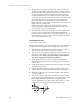

Table Of Contents
- Legal Notices
- Safety Notices
- In this Book
- Contents
- Quick Reference
- Installation
- Operating the Power Supply Locally
- Operating the Power Supply Remotely
- Language Reference
- SCPI Command Summary
- Calibration Commands
- Measure Commands
- Output Commands
- Source Commands
- [SOURce:]CURRent[:LEVel][:IMMediate][:AMPLitude]
|MIN|MAX [SOURce:]CURRent[:LEVel][:IMMediate][:AMPLitude]? [MIN|MAX] [SOURce:]CURRent[:LEVel]:TRIGgered[:AMPLitude] |MIN|MAX [SOURce:]CURRent[:LEVel]:TRIGgered[:AMPLitude]? [MIN|MAX] - [SOURce:]CURRent:PROTection:STATe ON|OFF [SOURce:]CURRent:PROTection:STATe?
- [SOURce:]VOLTage[:LEVel][:IMMediate][:AMPLitude]
|MIN|MAX [SOURce:]VOLTage[:LEVel][:IMMediate][:AMPLitude]? [MIN|MAX] [SOURce:]VOLTage[:LEVel]:TRIGgered[:AMPLitude] |MIN|MAX [SOURce:]VOLTage[:LEVel]:TRIGgered[:AMPLitude]? [MIN|MAX] - [SOURce:]VOLTage:LIMit:LOW
|MIN|MAX [SOURce:]VOLTage:LIMit:LOW? [MIN|MAX] - [SOURce:]VOLTage:PROTection:LEVel
|MIN|MAX [SOURce:]VOLTage:PROTection:LEVel? [MIN|MAX]
- [SOURce:]CURRent[:LEVel][:IMMediate][:AMPLitude]
- Status Commands
- STATus:PRESet
- STATus:OPERation[:EVENt]?
- STATus:OPERation:CONDition?
- STATus:OPERation:ENABle
STATus:OPERation:ENABle? - STATus:OPERation:NTR
STATus:OPERation:PTR STATus:OPERation:NTR? STATus:OPERation:PTR? - STATus:QUEStionable[:EVENt]?
- STATus:QUEStionable:CONDition?
- STATus:QUEStionable:ENABle
STATus:QUEStionable:ENABle? - STATus:QUEStionable:NTR
STATus:QUEStionable:PTR STATus:QUEStionable:NTR? STATus:QUEStionable:PTR? - *CLS
- *ESE *ESE?
- *ESR?
- *OPC *OPC?
- *SRE *SRE?
- *STB?
- *WAI
- System Commands
- Trigger Commands
- Programming Examples
- Specifications
- Verification and Calibration
- Verification
- Equipment Required
- Measurement Techniques
- Constant Voltage Tests
- Constant Current Tests
- Test Record Form – Agilent N5741A and N5761A
- Test Record Form – Agilent N5742A and N5762A
- Test Record Form – Agilent N5743A and N5763A
- Test Record Form – Agilent N5744A and N5764A
- Test Record Form – Agilent N5745A and N5765A
- Test Record Form – Agilent N5746A and N5766A
- Test Record Form – Agilent N5747A and N5767A
- Test Record Form – Agilent N5748A and N5768A
- Test Record Form – Agilent N5749A and N5769A
- Test Record Form – Agilent N5750A and N5770A
- Test Record Form – Agilent N5751A and N5771A
- Test Record Form – Agilent N5752A and N5772A
- Calibration
- Verification
- Service
- Compatibility
- Index
- Declaration of Conformity
Verification and Calibration Appendix B
Series N5700 User’s Guide 97
CV Source Effect
Test category = performance
This test measures the change in output voltage that results from a
change in AC line voltage from the minimum to maximum value
within the line voltage specifications.
1 Turn off the power supply and connect the ac power line through
a variable voltage transformer.
2 Connect a DVM and an electronic load as shown in figure A. Set
the variable voltage transformer to nominal line voltage.
3 Turn on the power supply and program the output current to its
maximum programmable value (Imax) and the output voltage to
its full-scale value.
4 Set the electronic load for the output’s full-scale current. The CV
annunciator on the front panel must be on. If it is not, adjust the
load so that the output current drops slightly.
5 Adjust the transformer to the low-line voltage (85 VAC for
100/120 nominal line; 170 VAC for 200/240 nominal line).
6 Record the output voltage reading from the DVM.
7 Adjust the transformer to the high-line voltage (132 VAC for
100/120 nominal line; 265 VAC for 200/240 nominal line).
8 Record the output voltage reading on the DVM. The difference
between the DVM reading in steps 6 and 8 is the source effect,
which should not exceed the value listed in the test record card
for the appropriate model under CV Source Effect.
CV Noise
Test category = performance
Periodic and random deviations in the output combine to produce a
residual AC voltage superimposed on the DC output voltage. This
residual voltage is specified as the rms or peak-to-peak output
voltage in the frequency range specified in Appendix A.
1 Turn off the power supply and connect the load resistor,
differential amplifier, and an oscilloscope (ac coupled) to the
output as shown in figure C. Use the xx Ω load for 750 W outputs;
use the xx Ω load for 1500 W outputs.
2 As shown in the diagram, use two BNC cables to connect the
differential amplifier to the + and − output terminals. Each cable
should be terminated by a 50 Ω resistor. The shields of the two
BNC cables should be connected together. Connect the output of
the differential amplifier to the oscilloscope with a 50 Ω
termination at the input of the oscilloscope.
3 Set the differential amplifier to multiply by ten, divide by one,
and 1 Megohm input resistance. The positive and negative inputs
of the differential amplifier should be set to AC coupling. Set the
oscilloscope’s time base to 5 ms/div, and the vertical scale to 10
mV/div. Turn the bandwidth limit on (usually 20 or 30 MHz), and
set the sampling mode to peak detect.